Replacing a microprocessor and heat sink
Use this information to replace a microprocessor and heat sink
Attention
When you handle static-sensitive devices, take precautions to avoid damage from static electricity. For details about handling these devices, see Handling static-sensitive devices.
Important:
- A startup (boot) microprocessor must always be installed in microprocessor connector 1 on the system board.
- To ensure correct server operation, make sure that you use microprocessors that are compatible and you have installed an additional DIMM for microprocessor 2. Compatible microprocessors must have the same QuickPath Interconnect (QPI) link speed, integrated memory controller frequency, core frequency, power segment, cache size, and type.
- Microprocessors with different stepping levels are supported in this server. If you install microprocessors with different stepping levels, it does not matter which microprocessor is installed in microprocessor connector 1 or connector 2.
- If you are installing a microprocessor that has been removed, make sure that it is paired with its original heat sink or a new replacement heat sink. Do not reuse a heat sink from another microprocessor; the thermal grease distribution might be different and might affect conductivity.
- If you are installing a new heat sink, remove the protective backing from the thermal material that is on the underside of the new heat sink.
- If you are installing a new heat-sink assembly that did not come with thermal grease, see Thermal grease for instructions for applying thermal grease.
- If you are installing a heat sink that has contaminated thermal grease, see Thermal grease for instructions for replacing the thermal grease.
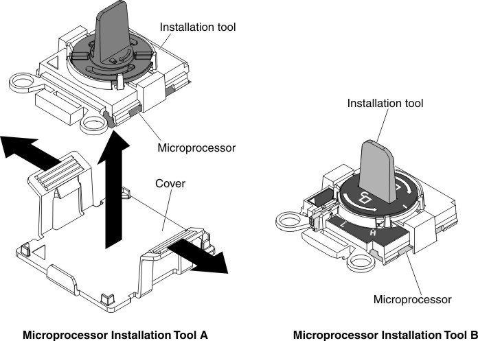
There are two types of microprocessor installation tools. The tools are similar in function and design, however Tool A has one setting for installing one size of microprocessor, and supports the following families of microprocessors: E5-26xx, E5-46xx. Installation Tool B has two settings for installing two different sizes of microprocessors. The settings that are marked on Tool B are L
for smaller low core microprocessors, and H
for larger high core microprocessors. Installation Tool B supports the following families of microprocessors: E5-26xx, E5-46xx, E5-26xx v2, E5-46xx v2.
Microprocessor Installation Tools A and B are shown in the following illustration.
Figure 1. Microprocessor installation tools
To install a microprocessor and heat sink, complete the following steps:
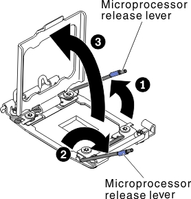
- Open the microprocessor socket release levers and retainer:Figure 2. Microprocessor socket levers and retainer disengagement
- Install the microprocessor on the microprocessor socket:
- Release the sides of the cover and remove the cover from the installation tool. The microprocessor is preinstalled on the installation tool.Figure 3. Installation tool cover removal
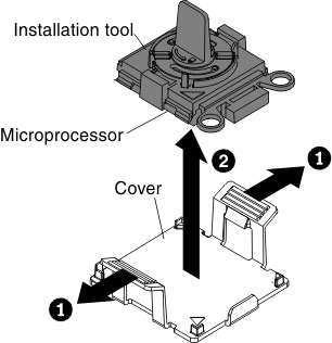 NoteDo not touch the microprocessor contacts. Contaminants on the microprocessor contacts, such as oil from your skin, can cause connection failures between the contacts and the socket.
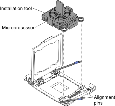
 - Align the installation tool with the microprocessor socket. The installation tool rests flush on the socket only if properly aligned.Figure 4. Installation tool alignment
- Install the microprocessor using the following instructions for your installation tool.
- If using Installation Tool A, twist the handle on the microprocessor tool assembly counterclockwise to the open position to insert the microprocessor into the socket, and lift the installation tool out of the socket.
- If using Installation Tool B, twist the handle of the installation tool assembly counterclockwise until the microprocessor is inserted into the socket, and lift the installation tool out of the socket. The following illustration shows the tool handle in the open position.
Figure 5. Installation tool handle adjustment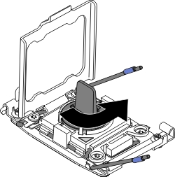 Figure 6. Installation Tool B
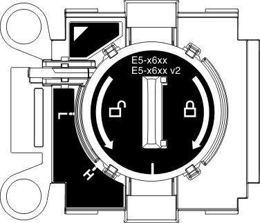 Attention
- Do not press the microprocessor into the socket.
- Make sure that the microprocessor is oriented and aligned correctly in the socket before you try to close the microprocessor retainer.
- Do not touch the thermal material on the bottom of the heat sink or on top of the microprocessor. Touching the thermal material will contaminate it.
- Release the sides of the cover and remove the cover from the installation tool. The microprocessor is preinstalled on the installation tool.
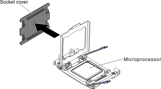
- Remove the microprocessor socket cover, tape, or label from the surface of the microprocessor socket, if one is present. Store the socket cover in a safe place.Figure 7. Socket cover removal
 AttentionWhen you handle static-sensitive devices, take precautions to avoid damage from static electricity. For details about handling these devices, see
Handling static-sensitive devices. - Close the microprocessor socket release levers and retainer:Figure 8. Microprocessor socket levers and retainer engagement
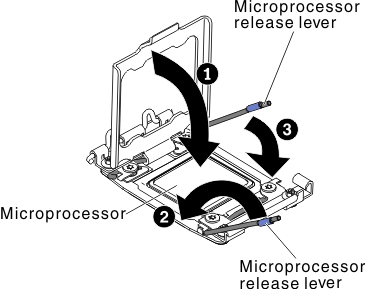
- Close the microprocessor retainer on the microprocessor socket.
- Identify which release lever is labeled as the first release lever to close and close it.
- Close the second release lever on the microprocessor socket.
- Install a heat sink on the microprocessor:Attention
- Do not set down the heat sink after you remove the plastic cover
- Do not touch the thermal grease on the bottom of the heat sink or set down the heat sink after you remove the plastic cover. Touching the thermal grease will contaminate it. If the thermal grease is contaminated, call service and support to request a replacement thermal grease kit. For information about installing the replacement thermal grease, see Thermal grease.
Figure 9. Heat-sink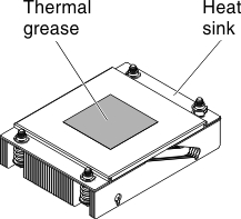 Figure 10. Heat-sink installation
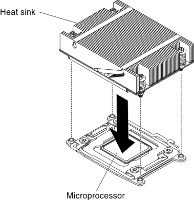
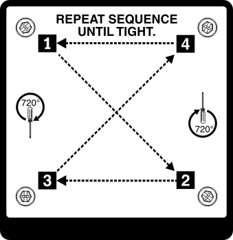
- Press firmly on the captive screws and tighten them with a screwdriver. The follow illustration shows the sequence in tightening the screws, which is also shown on top of the heat sink. Begin with the screw labeled as "1", then "2", "3" and finally "4". If possible, each screw should be rotated two full rotations at a time. Repeat until the screws are tight. Do not overtighten the screws by using excessive force. If you are using a torque wrench, tighten the screws to 8.5 Newton-meters (Nm) to 13 Nm (6.3 foot-pounds to 9.6 foot-pounds).NotePlease use Phillips screw driver No.0 to fasten screws.Figure 11. Screws sequence
Give documentation feedback