
Removing the system board

Use this information to remove the system board.

Note
  1. Before you replace the system board, make sure that you backup any features on demand (FoD) keys that were enabled. Remember to re-enable the features on demand (FoD) keys after installing the new system board. For more information on Features on Demand (FoD), including instructions for automating the activation and installation of the activation key by using ToolsCenter or Systems Director, see the Features on Demand User's Guide at https://fod.lenovo.com/lkms under the Help section.
  2. When you replace the system board, you must either update the server with the latest firmware or restore the pre-existing firmware from a diskette or CD image. Make sure that you have the latest firmware or a copy of the pre-existing firmware before you proceed.
Before you remove the system board from the server, take the following steps to save data, firmware, and configuration data:
  • Record all system configuration information, such as IMM IP addresses, vital product data, and the machine type, model number, serial number, Universally Unique Identifier, and asset tag of the server.
  • Using the Advanced Settings Utility (ASU), save the system configuration to external media.
  • Save the system-event log to external media.
Note
When you replace the system board, you must either update the server with the latest firmware or restore the pre-existing firmware that the customer provides on a diskette or CD image. Make sure that you have the latest firmware or a copy of the pre-existing firmware before you proceed.

To remove the system board, complete the following steps:

  1. Read the safety information that begins on page Safety and Installation guidelines.
  2. Turn off the server (see Turning off the server) and all attached peripheral devices. Disconnect all power cords; then, disconnect all external cables as necessary to replace the device.
  3. Pull the power supplies out of the rear of the server, just enough to disengage them from the server.
  4. Remove the server top cover (see Removing the server top cover).
  5. Remove the hot-swap rear hard disk drive cage (see Removing the hot-swap rear hard disk drive cage.
  6. Remove all PCI riser-card assemblies and adapters (see Removing a PCI riser-card assembly, Removing an adapter from the PCI riser-card assembly and Removing a ServeRAID adapter from the PCI riser-card assembly.
  7. Remove the air baffle (see Removing the air baffle).
  8. Remove all heat sinks and microprocessors, and set them aside on a static-protective surface for reinstallation (see Removing a microprocessor and heat sink.
    Note
    1. Be sure to keep the heat sink and microprocessor from each microprocessor socket of the old system board together so that you can install them on the new system board together. For example, when you remove the heat sink and microprocessor from microprocessor socket 1 of the old system board , install them both on the same socket on the new system board.
    2. Use an alcohol wipe to remove any thermal grease from the tabs on the microprocessor bracket frame on the old system board.
  9. Remove all DIMMs, and place them on a static-protective surface for reinstallation (see Removing a memory module).

    Important: Make a note of the location of each DIMM as you remove it, so that you can later reinstall it in the same connector.

  10. Remove the system battery (see Removing the system battery).
  11. Remove the USB embedded hypervisor flash device (see Removing a USB embedded hypervisor flash device.
  12. Disconnect all cables from the system board. Make a list of each cable as you disconnect it; you can then use this as a checklist when you install the new system board (see Internal cable routing and System-board internal connectors for more information).
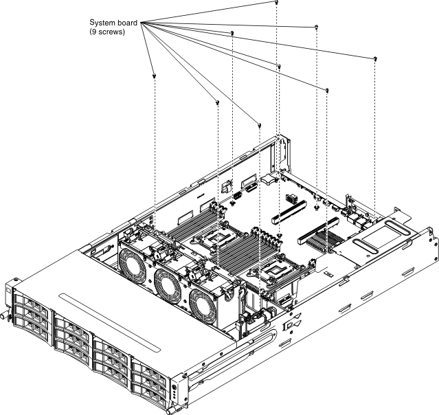
  13. Loosen the nine screws that secure the system board to the chassis.
    Figure 1. 9 screws
    9 screws
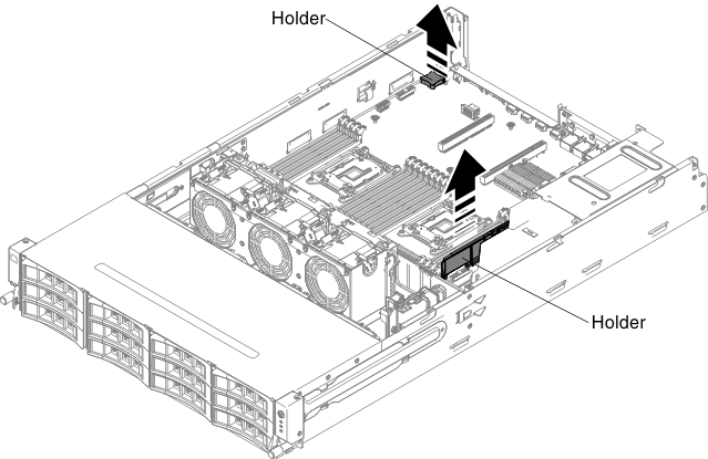
  14. Grasp two holders and slightly lift the system board.
    Figure 2. System board removal
    System board removal
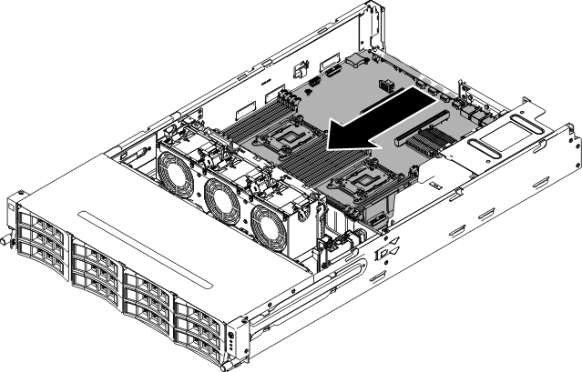
  15. Gently push the external input/output connectors out of their respective holes in the chassis.
    Figure 3. System board removal
    System board removal
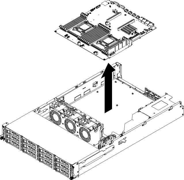
  16. Grasp the system board by the holders; then, carefully lift up the system board and remove it from the chassis, being careful not to damage any surrounding components.
    Figure 4. System board removal
    System board removal
  17. Remove the socket dust covers from the microprocessor sockets on the new system board and place them on the microprocessor sockets of the old system board that you are removing.
  18. If you are instructed to return the system board, follow all packaging instructions, and use any packaging materials for shipping that are supplied to you.
    Attention
    Make sure to place the socket covers for the microprocessor sockets on the system board before returning the system board.