Removing a microprocessor and heat sink
Use this information to remove a microprocessor and heat sink.
Attention
- Microprocessors are to be removed only by trained technicians.
- Be extremely careful, the pins on the socket are fragile. Any damage to the pins may require replacing the system board.
- Do not allow the thermal grease on the microprocessor and heat sink to come in contact with anything.
- Removing the heat sink from the microprocessor destroys the even distribution of the thermal grease and requires replacing the thermal grease.
- Do not touch the microprocessor contacts; handle the microprocessor by the edges only. Contaminants on the microprocessor contacts, such as oil from your skin, can cause connection failures between the contacts and the socket.
- Use the microprocessor installation tool that came with the new microprocessor to remove and install the microprocessor. Failure to use the microprocessor tool may cause damage to the pins on the socket. Any damage to the pins may require replacing the system board.
Note
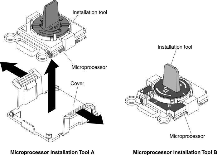
Be sure to use the installation tool that comes with your microprocessor installation tool assembly. The tools are similar in function and design, however Tool A has one setting for installing one size of microprocessor, and supports the following families of microprocessors: E5-26xx, E5-46xx. Installation Tool B has two settings for installing two different sizes of microprocessors. The settings that are marked on Tool B are
Lfor smaller low core microprocessors, and
Hfor larger high core microprocessors. Installation Tool B supports the following families of microprocessors: E5-26xx, E5-46xx, E5-26xx v2, E5-46xx v2.
Microprocessor Installation Tools A and B are shown in the following illustration.
Figure 1. Microprocessor installation tools
To remove a microprocessor and heat sink, complete the following steps:
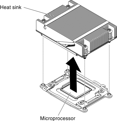
- Remove the heat sink:AttentionDo not touch the thermal material on the bottom of the heat sink. Touching the thermal material will contaminate it. If the thermal material on the microprocessor or heat sink becomes contaminated, you must wipe off the contaminated thermal material on the microprocessor or heat sink with the alcohol wipes and reapply clean thermal grease to the heat sink.Figure 2. Heat sink removal
- Open the microprocessor socket release levers and retainer:Figure 3. Microprocessor release lever and microprocessor bracket frame
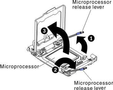
- Identify which release lever is labeled as the first release lever. Then release the microprocessor release lever by pressing down on the end, moving it to the side, and releasing it to the open (up) position.
- Open the second release lever on the microprocessor socket.
- Open the microprocessor bracket frame by lifting up the tab on the top edge. Keep the bracket frame in the open position.
NoteDo not touch the microprocessor contacts. Contaminants on the microprocessor contacts, such as oil from your skin, can cause connection failures between the contacts and the socket. - Remove the microprocessor from the socket.
- Select the empty installation tool and ensure that the handle is in the open position. If the installation tool handle is not in the open position, use the following instructions for your installation tool:
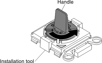
- If using Installation Tool A, twist the microprocessor installation tool handle counterclockwise to the open position.Figure 4. Installation tool handle adjustment
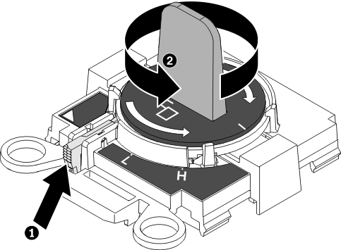
- If using Installation Tool B, 1 lift the interlock latch and hold it up while you 2 twist the microprocessor installation tool handle counterclockwise to the open position, and then release the interlock latch. The following illustration of the installation tool shows the location of the interlock latch and counterclockwise rotation of the handle before loading the microprocessor.Figure 5. Installation tool handle adjustment
- If using Installation Tool A, twist the microprocessor installation tool handle counterclockwise to the open position.
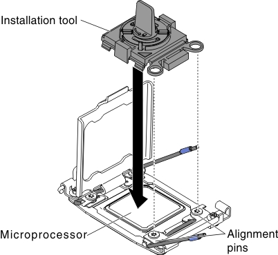
- Align the installation tool with the screws, as shown in the following graphic, and lower the installation tool on the microprocessor. The installation tool rests flush on the socket only when it is aligned correctly.Figure 6. Installation tool alignment
- Using the following instructions for your installation tool to remove the microprocessor.
- If using Installation Tool A, gently twist the handle clockwise to the closed position and lift the microprocessor out of the socket.
- If using Installation Tool B, gently twist the handle of the installation tool clockwise until it locks in the
H
orL
position, depending on the size of microprocessor, and then lift the microprocessor out of the socket.
Figure 7. Installation tool handle adjustment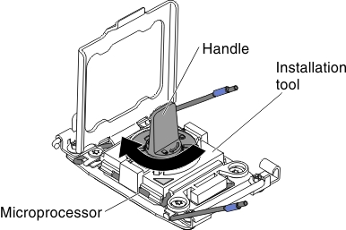
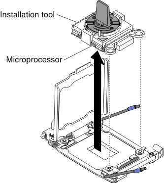
- Lift the microprocessor out of the socket.Figure 8. Installation tool removal
- Select the empty installation tool and ensure that the handle is in the open position. If the installation tool handle is not in the open position, use the following instructions for your installation tool:
Give documentation feedback