
Removing the system board

Use this information to remove the system board.

Attention
  1. When you replace the system board, you must either update the server with the latest firmware or restore the pre-existing firmware that the customer provides on a diskette or CD image. Make sure that you have the latest firmware or a copy of the pre-existing firmware before you proceed.
  2. Before removing any components or disconnecting any cables, keep note of their respective locations and how they are connected to the system board.
  3. When you replace the system board, make sure that you remove the Integrated Management Module Advanced Upgrade and place it on the new system board. For information about the Advanced Upgrade, see Using the remote presence and blue-screen capture features.
  4. Before you replace the system board, make sure that you back up any features on demand (FoD) keys that were enabled. Reactivate any Features on Demand features. Instructions for automating the activation of features and installing activation keys is in the Lenovo Features on Demand User's Guide. To download the document, go to the Lenovo Features on Demand website, log in, and click Help.

To remove the system board, complete the following steps:

  1. Read the safety information that begins on Safety, Handling static-sensitive devices, and Installation guidelines.
  2. Turn off the server and any attached devices.
  3. Turn off the peripheral devices and disconnect all power cords.
    Attention
    When you replace the system board, you must either update the server with the latest firmware or restore the pre-existing firmware that the customer provides on a diskette or CD image. Make sure that you have the latest firmware or a copy of the pre-existing firmware before you proceed.
  4. Pull the power supplies out of the rear of the server, just enough to disengage them from the server.
  5. Remove the cover (see Removing the cover).
  6. Remove all PCI riser-card assemblies and adapters (see Removing a PCI riser-card assembly and Removing an adapter).
  7. Remove the rear two hard-disk-drive kit, if any (see Removing the rear two hard-disk-drive kit).
  8. Remove the air baffle (see Removing the air baffle).
  9. Remove the dual-port network adapter (see Removing the dual-port network adapter).
  10. Remove the ServeRAID adapter memory module (see Removing the ServeRAID adapter memory module).
  11. Remove the memory modules and set them aside on a static-protective surface for reinstallation (see Removing a memory module).
    Note
    Make a note of the location of each DIMM as you remove it, so that you can later reinstall it in the same connector.
  12. Remove the USB embedded hypervisor flash device (see Removing a USB embedded hypervisor flash device).
  13. (Trained technician only) Remove all heat sinks and microprocessors, and set them aside on a static-protective surface for reinstallation (see Removing a microprocessor and heat sink).
    Attention
    1. Remove the socket covers from the microprocessor sockets on the new system board and place them on the microprocessor sockets of the system board you are removing.
    2. Do not allow the thermal grease to come in contact with anything, and keep each heat sink paired with its microprocessor for reinstallation. Contact with any surface can compromise the thermal grease and the microprocessor socket. A mismatch between the microprocessor and its original heat sink can require the installation of a new heat sink.
  14. Remove the system battery (see Removing the system battery).
  15. Remove the hot-swap fans (see Removing a hot-swap fan).
  16. Remove the fan bracket (see Removing the fan bracket).
  17. Disconnect all cables from the system board. Make a list of each cable as you disconnect it; you can then use this as a checklist when you install the new system board (see Internal cable routing and connectors for more information).
    Attention
    Disengage all latches, release tabs or locks on cable connectors when you disconnect all cables from the system board. Failing to release them before removing the cables will damage the cable sockets on the system board. The cable sockets on the system board are fragile. Any damage to the cable sockets may require replacing the system board.
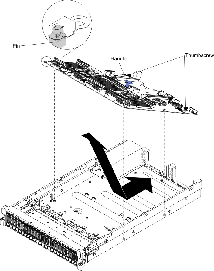
  18. Pull out and lift up the pin and the thumbscrews on each side of the system board.
    Figure 1. System board removal
    System board removal
  19. Remove the socket covers from the microprocessor sockets on the new system board and place them on the microprocessor sockets of the old system board that you are removing.
  20. If you are instructed to return the system board, follow all packaging instructions, and use any packaging materials for shipping that are supplied to you.
    Attention
    Make sure to place the socket covers for the microprocessor sockets on the system board before returning the system board.