Removing a microprocessor and heat sink
Use this information to remove a microprocessor and heat sink.
Attention
- Be extremely careful when handling the microprocessor, the microprocessor socket contacts are very fragile.
- Do not touch the microprocessor contacts. Contaminants on the microprocessor contacts, such as oil from your skin, can cause connection failures between the contacts and the socket.
- Do not use any tools or sharp objects to lift the locking levers on the microprocessor socket. Doing so might result in permanent damage to the system board.
- Do not allow the thermal grease on the microprocessor and heat sink to come in contact with anything. Contact with any surface can compromise the thermal grease and the microprocessor socket.
- Each microprocessor socket must always contain either a socket cover or a microprocessor and heat sink.
- When removing multiple microprocessors, open one microprocessor socket at a time to avoid damaging other microprocessor socket contacts.
- Be sure to use only the installation tools provided with the new microprocessor to remove or install the microprocessor. Do not use any other tool.
- The microprocessor installation tool has the microprocessor installed on the tool, and may have a protective cover over the microprocessor. Do not use the tool, or remove the cover until you are instructed to do so.
Note
This procedure for removing a microprocessor and heat sink also apply when removing a microprocessor and heat sink from the microprocessor and memory expansion tray.
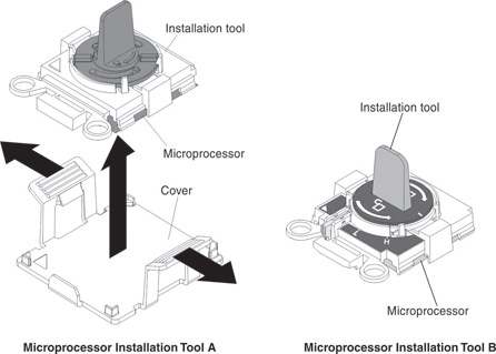
There are two types of microprocessor installation tools. The tools are similar in function and design; but, have a major difference.
Important
Be sure to use the installation tool that comes with your microprocessor installation tool assembly.
- Installation Tool A has one setting for installing one size of microprocessor that supports E5-26xx and E5-46xx microprocessors.
- Installation Tool B supports E5-26xx, E5-46xx, E5-26xx v2, and E5-46xx v2 microprocessors. Installation Tool B has two settings for installing two different sizes of microprocessors. The settings on Tool B are:
L
for smaller low core microprocessorsH
for larger high core microprocessors
Microprocessor Installation Tools A and B are shown in the next illustration.
To remove a microprocessor and heat sink, complete the following steps:
- Remove the heat sink.
- Loosen all the captive screws on the heat sink, rotating each screw one full turn until each screw is loose.
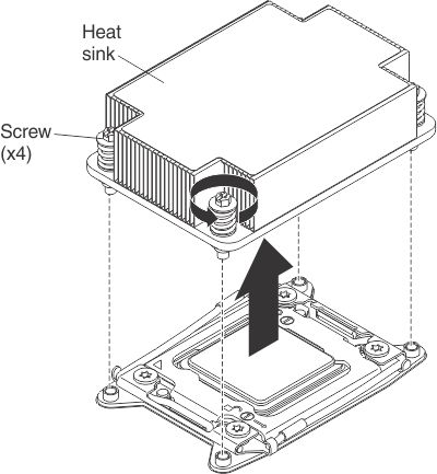
- Loosen all the captive screws on the heat sink, rotating each screw one full turn until each screw is loose.
- Open the microprocessor socket release levers and retainer.
- Open the microprocessor socket release levers and retainer in the order that is shown.
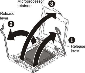
- Open the microprocessor socket release levers and retainer in the order that is shown.
- Remove the microprocessor from the socket.
- Select the empty installation tool and ensure that the handle is in the open position. If the installation tool handle is not in the open position, use the following instructions for your installation tool:
- If using Installation Tool A, twist the microprocessor installation tool handle counterclockwise to the open position.
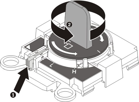
- If using Installation Tool B:
- Lift the interlock latch and raise the latch up.
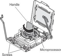
- While holding the interlock latch up, twist the microprocessor installation tool handle counterclockwise to the open position; then, release the interlock latch.
The following illustration of Installation Tool B shows the location of the interlock latch and counterclockwise rotation of the handle before loading the microprocessor.
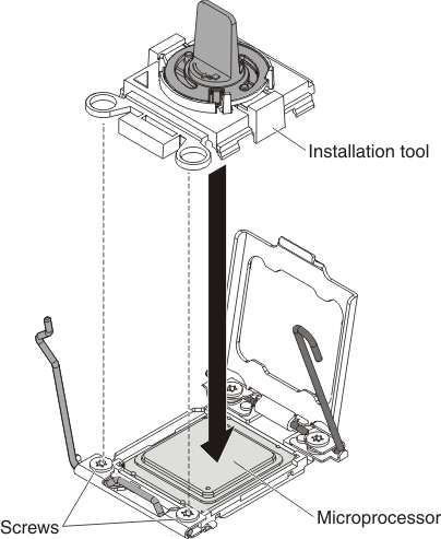
- Align the holes on the installation tool with the screws on the microprocessor bracket, then lower the microprocessor installation tool down over the microprocessor. The installation tool rests flush on the socket only if it is aligned correctly.
- Place the microprocessor on a static-protective surface. Remove the microprocessor from the socket using the appropriate instructions for your installation tool.
- If using Installation Tool A, gently twist the handle clockwise to the closed position and lift the microprocessor out of the socket.
- If using Installation Tool B, gently twist the handle of the installation tool clockwise until it locks in the
H
orL
position, depending on the size of microprocessor; then, lift the microprocessor out of the socket.
- Select the empty installation tool and ensure that the handle is in the open position. If the installation tool handle is not in the open position, use the following instructions for your installation tool:
Give documentation feedback