
Removing the system board

Use this information to remove the system board.

Before you remove the system board from the server, take the following steps to save data, firmware, and configuration data:
  • Record all system configuration information, such as integrated management module II (IMM2) IP addresses, vital product data, and the machine type, model number, serial number, Universally Unique Identifier, and asset tag of the server.
  • Using the Advanced Settings Utility (ASU), save the system configuration to external media.
  • Save the system-event log to external media.
Note
When you replace the system board, you must update the server with the latest firmware or restore the pre-existing firmware that the customer provides on a CD or DVD image. Make sure that you have the latest firmware or a copy of the pre-existing firmware before you proceed.

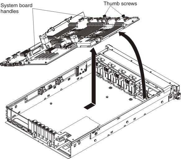
To remove the system board, complete the following steps:

  1. Read the safety information and installation guidelines, see Safety and Installation guidelines).
  2. Turn off the server (see Turning off the server) and all attached peripheral devices. Disconnect all power cords; then, disconnect all external cables as necessary to replace the device.
  3. If the server is in a rack, slide the server out of the rack.
  4. Remove the server cover (see Removing the server top cover).
  5. Remove the fan cage assembly (see Removing the fan cage assembly).
  6. Remove the DIMM air baffle, if one is installed (see Removing the DIMM air baffle).
  7. Slide the power supplies out of the bays slightly to disengage them from the connectors.
  8. Remove the microprocessor and memory expansion tray, if one is installed (see Removing the microprocessor and memory expansion tray assembly).
  9. Remove the microprocessor air baffle (see Removing the microprocessor air baffle).
  10. Disconnect all cables from the system board. Make a list of each cable as you disconnect it; you can then use this as a checklist when you install the new system board.
  11. Disconnect the remote RAID flash power module cable from the adapter and remove the flash power module from the trays located on top of the USB/video assembly, if any are installed (see Removing a RAID adapter flash power module).
  12. Remove the DIMMs from the system board and set them aside on a static-protective surface for reinstallation (see Removing a memory module).
    Note
    Make a note of the location of each DIMM as you remove it, so that you can later reinstall it in the same connector.
  13. Remove the RAID cache cards from the system board, if any are installed (see Removing a RAID cache card).
  14. Remove the power interposer card assembly, if one is installed (see Removing the power interposer for redundant power supply card assembly).
  15. Remove the PCIe riser-card assembly, if it is installed (see Removing a PCI riser-card assembly).
  16. Remove any adapters that are installed on the system board (see Removing an adapter).
  17. Remove the Ethernet adapter, if one is installed (see Removing the Intel I350-T4 ML2 Quad-Port GbE Adapter for System x or Removing the ML2 Dual-port 10Gbase-T Adapter for System x or ML2 Dual-port 10 GbE SFP+ Adapter for System x).
  18. Remove the USB embedded hypervisor flash device (see Removing a USB embedded hypervisor flash device).
  19. Remove all heat sinks and microprocessors, and set them aside on a static-protective surface for reinstallation (see Removing a microprocessor and heat sink).
    Note
    1. Remove the socket covers from the microprocessor frame brackets on the new system board and place them on the microprocessor sockets of the old system board that you are removing.
    2. Use an alcohol wipe to remove any thermal grease from the tabs on the microprocessor bracket frame on the old system board.
    3. Use the microprocessor tool that comes in the system board FRU to remove and replace microprocessors.
    4. Remove the microprocessors from the old system board and place them directly onto the new system board sockets. Keep the heat sink and microprocessor from each microprocessor socket of the old system board together so that you can install them on the new system board on the same socket together. For example, when you remove the heat sink and microprocessor from microprocessor socket 1 of the old system board, install them both on the same socket (socket 1) on the new system board.
  20. Remove the backplanes and cables, if necessary to access and remove the system board.
  21. Loosen the thumbscrews (near the front of the server) that secure the system board to the server and slide the system board toward the front of the server.
    Note
    Remove the drive backplanes, if necessary.

    remove system board

  22. Grasp both system-board handles and lift up the left side of the system board slightly and carefully remove it from the chassis, being careful not to damage any surrounding components.
    Note
    Use the system-board handles to lift the system board only. Do not attempt to lift the server using the system board handles.
  23. If you are instructed to return the system board, follow all packaging instructions, and use any packaging materials for shipping that are supplied to you.