
Replacing the system board

Use this information to replace the system board.

Note
  • When you reassemble the components in the server, be sure to route all cables carefully so that they are not exposed to excessive pressure and so that they do not get pinched when you reinstall the system board.
  • When you replace the system board, you must either update the server with the latest firmware or restore the pre-existing firmware that the customer provides on a diskette or CD image. Make sure that you have the latest firmware or a copy of the pre-existing firmware before you proceed. See Updating the firmware and Updating the Universal Unique Identifier and DMI/SMBIOS data for more information.
  • Reactivate any Features on Demand features. Instructions for automating the activation of features and installing activation keys is in the System x Features on Demand User's Guide. To download the document, go to Using Lenovo Features on Demand, log in, and click Help.

Important: Some cluster solutions require specific code levels or coordinated code updates. If the device is part of a cluster solution, verify that the latest level of code is supported for the cluster solution before you update the code.

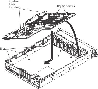
To install the system board, complete the following steps:

  1. Read the safety information, see Safety and Installation guidelines.
  2. Align the system board with the slots on the side of the chassis and lower the right side into the chassis first; then, lower the other side of the system board into the chassis.

    replace system board

  3. Slide the system-board toward the rear of the server to secure it in place.
  4. Tighten the thumbscrews to secure the system board to the chassis.
  5. Reinstall the DIMMs onto the system board (see Replacing a memory module).
  6. Reinstall the heat sinks (see Replacing a microprocessor and heat sink).
    Note
    • Make sure that the socket covers from the microprocessor frame brackets on the new system board were placed on the microprocessor sockets on the old system board that you removed.
    • Use an alcohol wipe to remove any thermal grease from the tabs on the microprocessor bracket frame on the old system board.
    • Use the microprocessor tool that comes in the system board FRU to remove and replace microprocessors.
    • Remove and keep the heat sink and microprocessor from each microprocessor socket of the old system board together and install them on the new system board on the same socket together. For example, when you removed the heat sink and microprocessor from microprocessor socket 1 of the old system board , you installed them both on the same socket (socket 1) on the new system board.
  7. Reinstall the microprocessor air baffle (see Replacing the microprocessor air baffle).
  8. Reinstall the USB embedded hypervisor flash device, if you removed it earlier (see Replacing a USB embedded hypervisor flash device).
  9. Reinstall the PCI riser-card assembly, if any were installed (see Replacing a PCI riser-card assembly).
  10. Reinstall any adapters that were removed from the system board, if you removed them earlier (see Replacing an adapter).
  11. Reinstall the RAID cache cards, if you removed them earlier (see Replacing a RAID cache card).
  12. Reinstall the Ethernet adapter, if you removed it earlier (see Replacing the Intel I350-T4 ML2 Quad Port GbE Adapter for System x or Replacing the ML2 Dual-port 10Gbase-T Adapter for System x or ML2 Dual-port 10 GbE SFP+ Adapter for System x).
  13. Reinstall the power interposer card assembly, if you removed it earlier (see Replacing a power interposer redundant power supply card assembly).
  14. Reconnect the cables that you disconnected earlier to the system board.
  15. Reconnect the remote RAID flash power module cable to the adapter and install the RAID flash power module in the trays located on the top of the front USB/video assembly, if you removed it earlier.
  16. Reinstall the DIMM air baffle, if one was installed (see Replacing the DIMM air baffle).
  17. Reinstall the microprocessor and memory expansion tray, if one was installed (see Replacing the microprocessor and memory expansion tray assembly).
  18. Slide the power supplies back into the bays until they click into place.
  19. Reinstall the backplanes and cables, if you removed them.
  20. Reinstall the fan cage assembly (see Replacing the fan cage assembly).
  21. Reinstall the cover (see Replacing the server top cover).
  22. Slide the server into the rack.
  23. Reconnect the power cords and any cables that you removed.
  24. Turn on the peripheral devices and the server.

Important: Perform the following updates: