Installing the 4x2.5-inch NVMe PCIe Gen3 solid state drive backplane
Use this information for instructions on how to install the 4x2.5-inch NVMe PCIe Gen3 solid state drive backplane assembly.
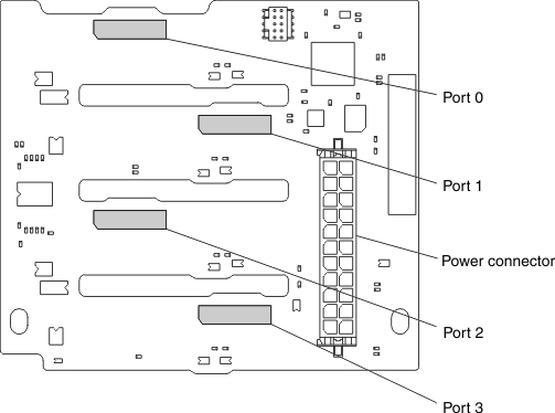
The following is an illustration of the 4x2.5-inch NVMe PCIe Gen3 solid state drive backplane:
- Install a backplane filler in the bottom backplane bay, if no backplane is installed.
- Install individual drive fillers in all unused drive bays.
- The 4x2.5-inch NVMe PCIe Gen3 solid state drive backplane can support up to four 2.5-inch NVMe PCIe solid state drives.
- You can install one 4x2.5-inch NVMe PCIe Gen3 solid state drive backplane.
- Install the 4x2.5-inch NVMe PCIe Gen3 solid state drive backplane in the top backplane bay only.
- You can install an additional SAS/SATA backplane in the lower backplane bay.
- The drive IDs assigned by IMM2 match the IDs that are indicated on the server front bezel.
- The operating system and uEFI report the hard disk drives attached to the 4x2.5-inch NVMe PCIe Gen3 solid state drive backplane as PCI devices.
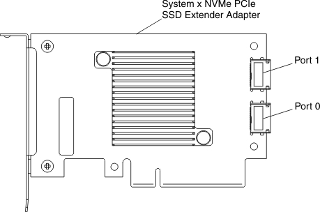
The backplane PCIe signal cable is attached to the NVMe PCIe Gen3 solid state drive extender adapter. The following is an illustration of the connectors on the adapter.
Before you connect the NVMe PCIe Gen3 solid state drive backplane to the NVMe PCIe Gen3 solid state drive extender adapter, consider the following information:
- Each NVMe PCIe Gen3 solid state drive extender adapter supports two NVMe solid state drives.
- You must install two NVMe PCIe Gen3 solid state drive extender adapters to support four PCIe drives.
- The following table describes the cabling and installation of the NVMe PCIe Gen3 solid state drive backplane to the NVMe PCIe Gen3 solid state drive extender adapter.
Table 1. NVMe PCIe Gen3 solid state drive backplane to the NVMe PCIe Gen3 solid state drive extender adapter cabling and installation. three column table
NVMe PCIe adapter installation Install in PCIe slot PCIe signal cable connections First NVMe PCIe adapter Standard I/O book slot 11 Connect adapter port 0 to backplane port 0 Connect adapter port 1 to backplane port 1 Second NVMe PCIe adapter Standard I/O book slot 12 Connect adapter port 0 to backplane port 2 Connect adapter port 1 to backplane port 3
To install the 4x2.5-inch NVMe PCIe Gen3 solid state drive backplane, complete the following steps:
- Before you begin, read Safety and Installation guidelines.
- Turn off the server (see Turning off the server) and all attached peripheral devices. Disconnect all power cords; then, disconnect all external cables from the server.
- Remove the storage book from the server (see Removing the storage book).
- If a backplane filler panel is installed in the backplane bay in which you are installing the backplane, remove the backplane filler panel.
- Insert the backplane tabs into the slots on the left side of the backplane cage and rotate the drive backplane assembly forward until the backplane locks in place in the retention latch.
- Connect the power cable to the power connector on the drive backplane.
- Connect the PCIe signal cable to the drive backplane and to the adapter.
If you have other devices to install or remove, do so now. Otherwise, go to Completing the installation.