Replacing a Chassis Management Module
Use these instructions to install a CMM in the Flex System Carrier-Grade chassis. You can install a CMM while the chassis is powered on.
Before you install the CMM, complete the following steps:
- Read the installation instructions in the documentation that comes with the CMM.
- If you are installing a standby CMM, see ../com.lenovo.acc.cmm.doc/redundancy_prep_cmm.html.
- If you have not already done so, touch the static-protective package that contains the replacement CMM to an unpainted metal part of the chassis or any unpainted surface on any other grounded rack component for at least 2 seconds.
- Remove the CMM from its static-protective package.
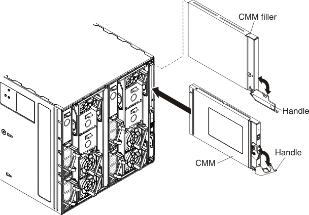
To install a Chassis Management Module (CMM), complete the following steps.
After you install the CMM, complete the following steps:
- Replace any components that you removed to gain access to the CMM bay.
- Connect all cables to the CMM.
- Depending on your system configuration, you might have to manually configure the CMM:
- If this is a standby CMM and you followed the instructions in ../com.lenovo.acc.cmm.doc/redundancy_prep_cmm.html, no configuration is necessary.NoteThe standby
CMM receives the configuration and status information automatically from the primary CMM. The transfer of information to the standby CMM can take up to 45 minutes after it is installed. - If this is the only CMM in the chassis, configure the new CMM:
- If you saved the CMM configuration file before you replaced the CMM, you can apply the saved configuration file to the replacement CMM.
- In the CMM web interface, saved configurations are applied in the Manage Configuration page (select Configuration from the Mgt Module Management menu). All fields and options are described in the CMM web interface online help.
- In the CMM command-line interface (CLI), use the read command (see ../com.lenovo.acc.cmm.doc/cli_command_read.html for information about commands).
- If you did not save the CMM configuration file before you replaced the CMM, see ../com.lenovo.acc.cmm.doc/configuring_the_cmm.html for information.
- If you saved the CMM configuration file before you replaced the CMM, you can apply the saved configuration file to the replacement CMM.
- If this is a standby CMM and you followed the instructions in ../com.lenovo.acc.cmm.doc/redundancy_prep_cmm.html, no configuration is necessary.
Give documentation feedback