Replacing an adapter
The following notes describe the types of adapters that the server supports and other information that you must consider when you install an adapter.
- Locate the documentation that comes with the adapter and follow those instructions in addition to the instructions in this section.
- Do not set the maximum digital video adapter resolution above 1600 x 1200 at 75 Hz for an LCD monitor. This is the highest resolution that is supported for any add-on video adapter that you install in the server.
- Any high-definition video-out connector or stereo connector on any add-on video adapter is not supported
- The server does not support full-length, full-height PCI adapters or legacy 5V PCI adapters.
- When you install any PCI adapter, the power cords must be disconnected from the power source before you remove the PCI Express riser-card assembly. Otherwise, the active power management event signal will be disabled by the system-board logic, and the Wake on LAN feature might not work. However, after the server is powered-on locally, the active power manager active power management event signal will be enabled by the system-board logic.
The Intel X710 2x10GbE SFP+ Adapter supports 10-Gbps transfer rate only.
- Pay attention to the following before installing any PCI adapter.
- Pay attention to the following PCI adapter configuration table before installing any PCI adapter.
Table 1. Adapter configurations. Four column parts listing table for adapter description, option part number, PCI riser 1, and PCI riser 2.
Description Option part number PCI riser 1 PCI riser 2 Intel X540 ML2 Dual Port 10GbaseT Adapter 00D1994 Seven fans required Seven fans required NoteYou can purchase the System x3550 M5 Fan Gen 2 (option part number: 00MV373) to acquire two additional fans for your server. - The server provides two PCI riser-card slots on the system board.The following table lists the supported PCI riser-card assembly configurations in the server.
Table 2. Configuration 1 (HX1310 only). The PCI riser-card assembly configuration 1 table description table.
Configuration 1 Configuration Number of microprocessors installed PCI riser-card assembly connector 1 on system board PCI riser-card assembly connector 2 on system board Slot 1 Slot 2 Slot 3 - Three low-profile slots
One x1/x4/x8/x16 low-profile x1/x4/x8 low-profile x1/x4/x8 low-profile Table 3. Configuration 2 (HX2310-E, HX3310, HX3310-F). The PCI riser-card assembly configuration 2 table description table.
Configuration 2 Configuration Number of microprocessors installed PCI riser-card assembly connector 1 on system board PCI riser-card assembly connector 2 on system board Slot 1 Slot 2 Slot 3 - Three low-profile slots
Two x1/x4/x8/x16 low-profile x1/x4/x8/x16 low-profile x1/x4/x8/x16 low-profile
Note
Always refer to the above configurations when installing a PCI riser-card assembly. Do not install a PCI-riser card assembly that does not follow the above configurations.
The instructions in this section apply to any PCI adapter (for example, video graphics adapters or network adapters).
To replace an adapter, complete the following steps:
Note
If your adapter was previously configured, back up or record its configuration information, if possible, before replacing the adapter. See the documentation for your adapter for information and instructions.
- Insert the adapter into the PCI riser-card assembly, aligning the edge connector on the adapter with the connector on the PCI riser-card assembly. Press the edge of the connector firmly into the PCI riser-card assembly. Make sure that the adapter snaps into the PCI riser-card assembly securely. The following illustrates show the different types of PCI riser-card assemblies:Figure 1. Adapter installation into a PCI riser-card assembly that has one low-profile slot (for PCI riser-card assembly connector 1 on system board)
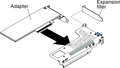 Figure 2. Adapter installation into a PCI riser-card assembly that has one low-profile slot and one full-height half-length slot (for PCI riser-card assembly connector 2 on system board)
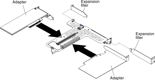 AttentionWhen you install an adapter, make sure that the adapter is correctly seated in the riser-card assembly and that the riser-card assembly is securely seated in the riser-card connector on the system board before you turn on the server. An incorrectly seated adapter might cause damage to the system board, the riser-card assembly, or the adapter.
Give documentation feedback