Install a PCIe adapter into the riser cage
Use this information to install a PCIe adapter into the riser cage.
- Read the following section(s) to ensure that you work safely.
If the compute-expansion node assembly is installed in the enclosure, remove it (see Remove the compute-expansion node assembly from the enclosure).
Remove the rear cable cover (see Remove the rear cable cover).
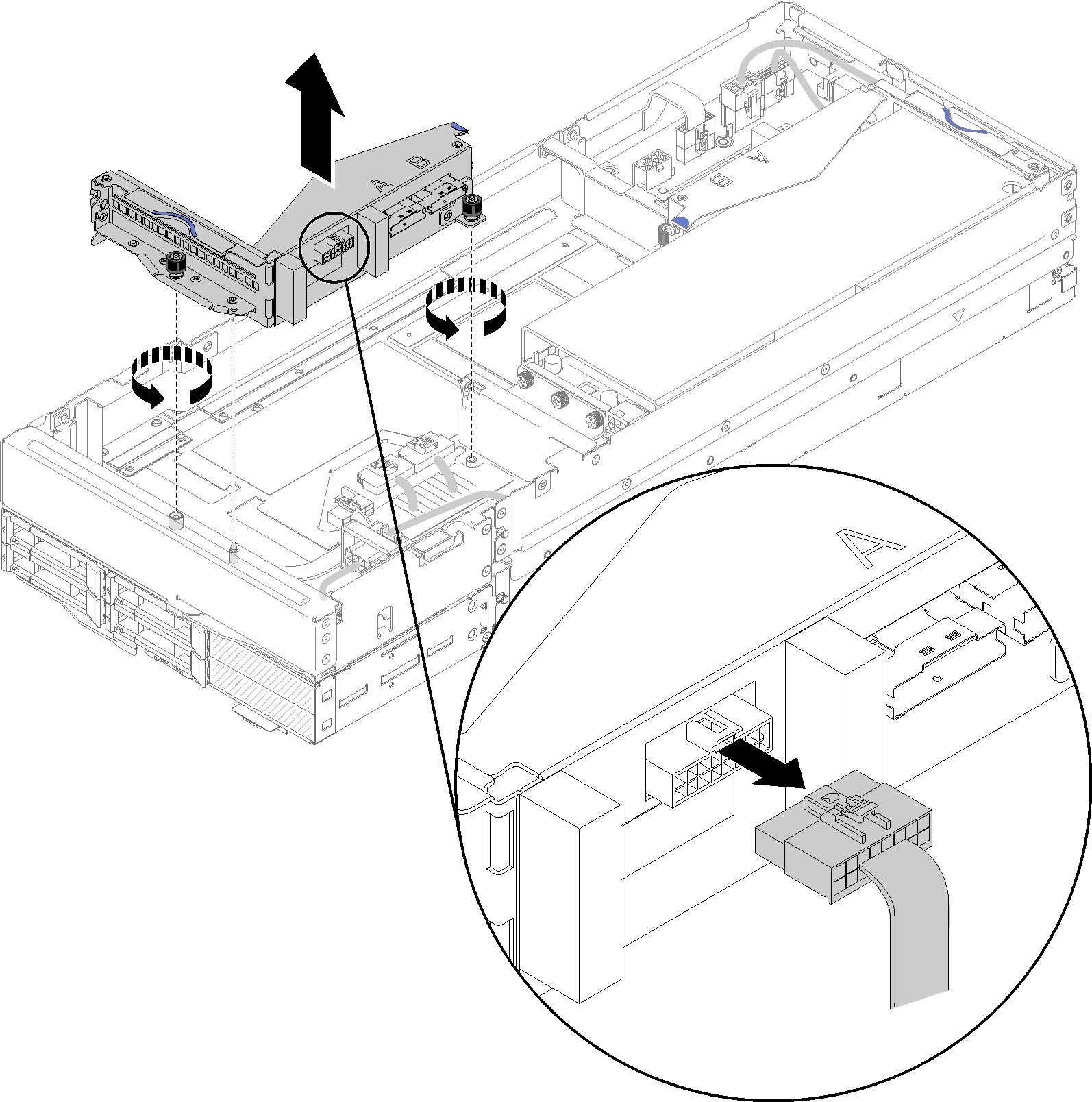
- If an adapter has been installed in the riser cage, remove the PCIe riser assembly from the expansion node assembly (see Remove a PCIe riser assembly from the compute-expansion node assembly), and remove the adapter from the riser cage (see Remove a PCIe adapter from the riser cage). If no adapter has been installed in the riser cage, disconnect the front riser miscellaneous cable first if you are removing the front riser cage; then, loosen the two captive screws to remove the riser cage from the node.Figure 1. Disconnecting the front riser miscellaneous cable from the riser cage and removing the riser cage from the expansion node
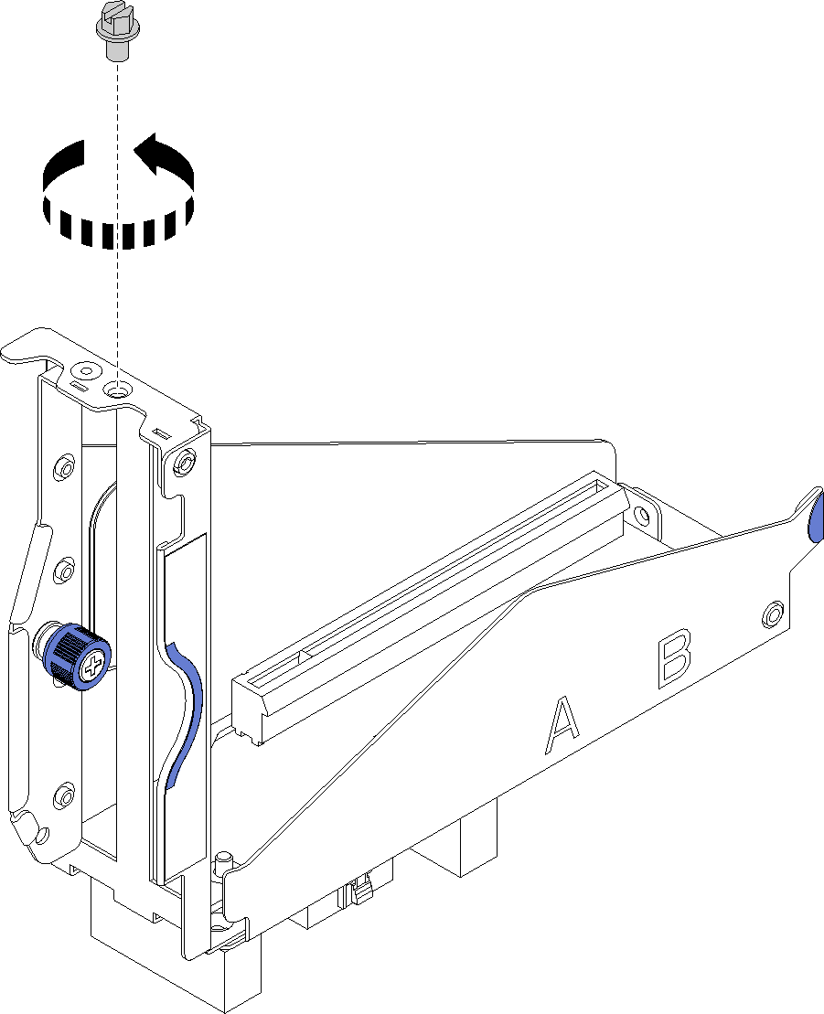
- If no adapter has been installed in the riser cage, remove the screw from the riser cage. Figure 2. Removing the screw from the riser cage
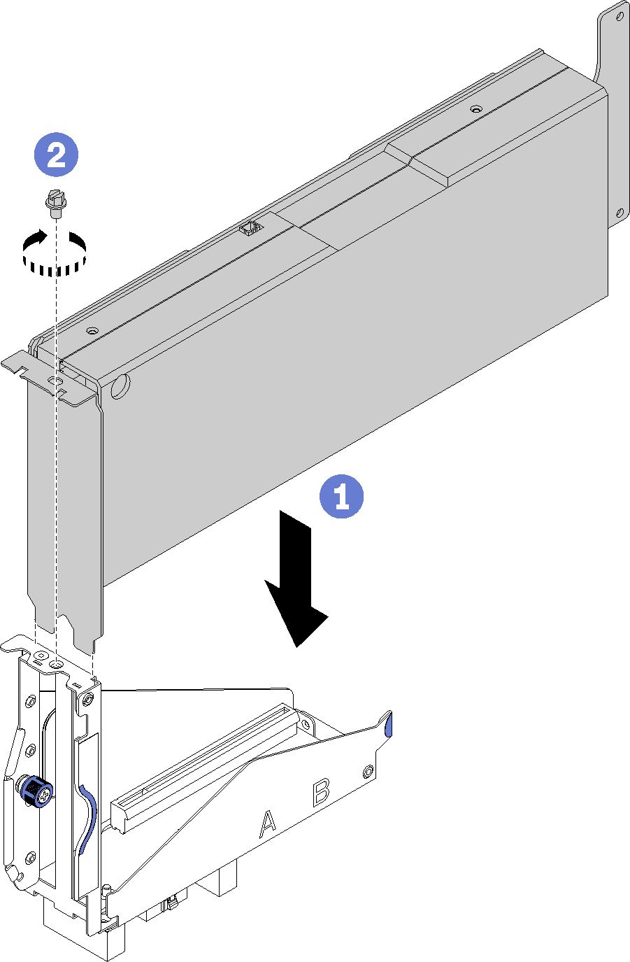
- Slide the adapter into the slot on the riser cage; then, fasten the screw to secure the adapter.Figure 3. Installing an adapter into the riser cage
- Connect the auxiliary power cable that comes with the adapter as illustrated.Figure 4. Connecting the auxiliary power cable to the adapter connectors
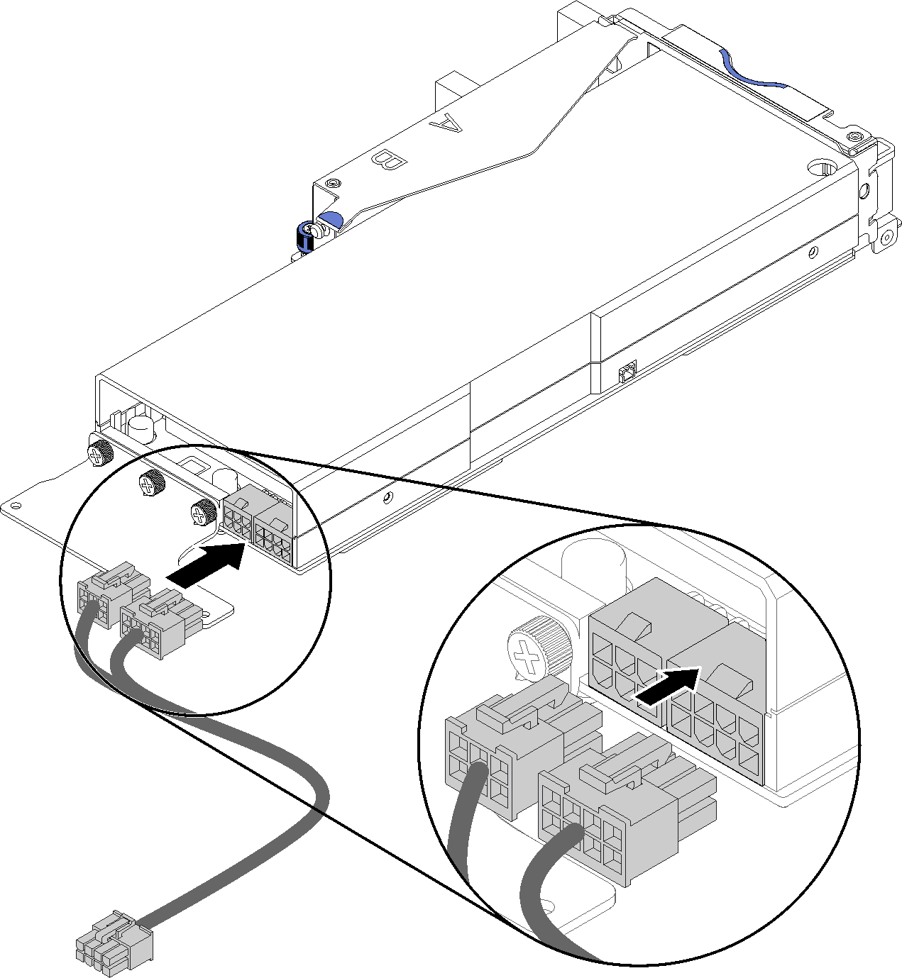 AttentionThe PCIe adapter may come with more than one auxiliary power cable, and it is of crucial importance to adopt the cable specifically meant for SD530. Carefully examine the end of cable for PCIe expansion node, and make sure it is exactly the same as illustrated.Figure 5. The connector of the auxiliary cable for SD530
 Note
NoteThe auxiliary power cable that comes with your adapter might look different from that in the illustration.
The location of connectors might be different from that in the illustration.
After you install the PCIe adapter into the riser cage, complete the following steps:
Install the PCIe riser assembly into the PCIe expansion node (see Install a PCIe riser assembly into the PCIe expansion node assembly).
Install the rear cable cover (see Install the rear cable cover).
Install the PCIe expansion node assembly into the enclosure (see Install the compute-expansion node assembly into the enclosure).
Power on the compute node.
Demo video