Remove a PCIe riser assembly from the compute-expansion node assembly
Use this information to remove a PCIe riser assembly from the compute-expansion node assembly.
- Read the following section(s) to ensure that you work safely.
If the compute-expansion node assembly is installed in the enclosure, remove it (see Remove the compute-expansion node assembly from the enclosure).
Remove the rear cable cover (see Remove the rear cable cover).
Remove the front PCIe riser assembly
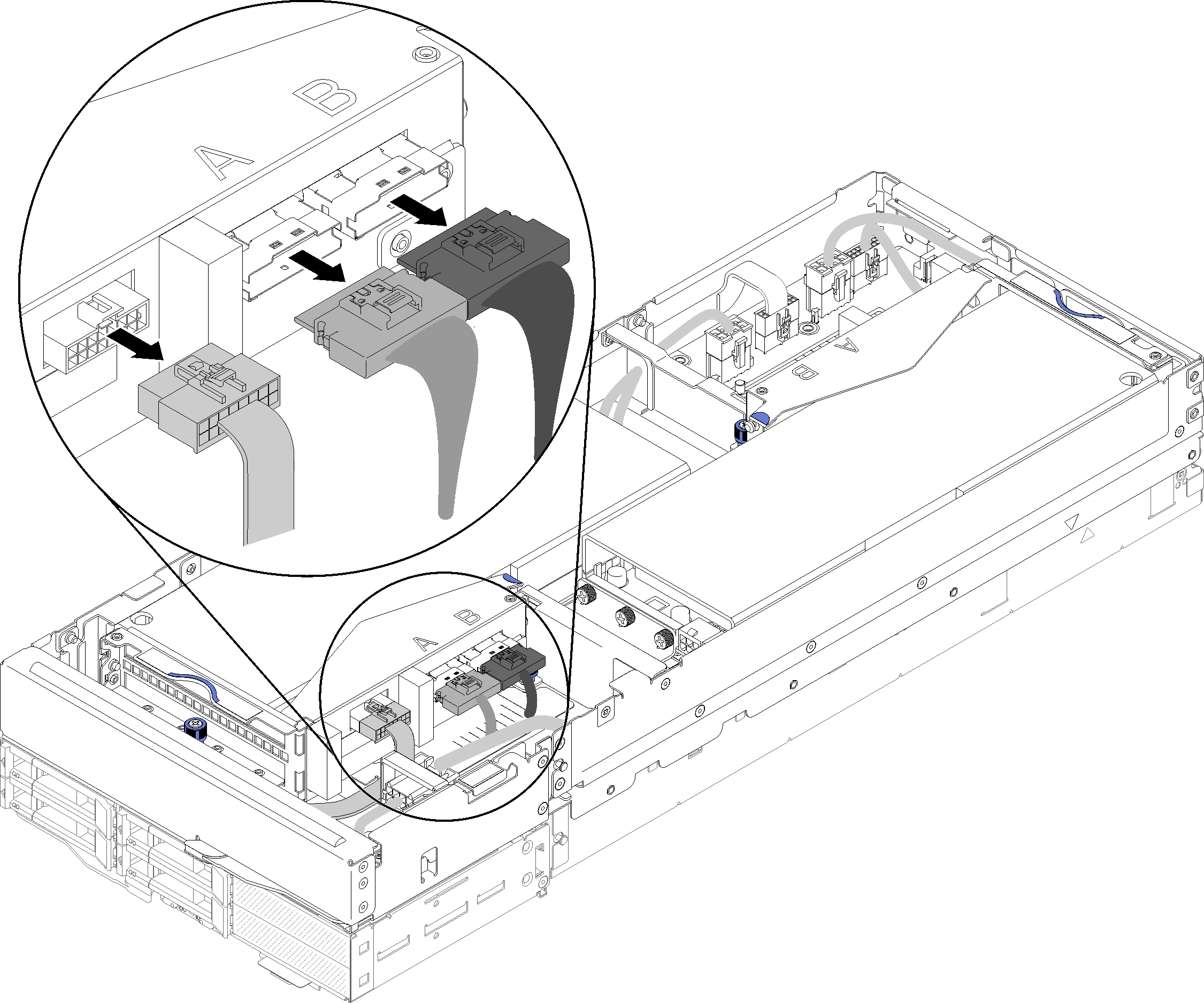
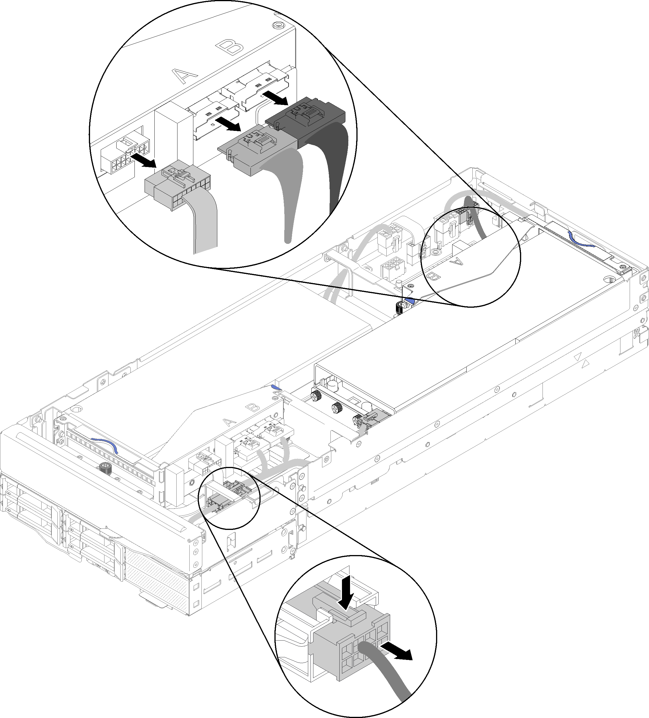
- Disconnect PCIe#3-A, PCIe#4-B and the riser miscellaneous cable from the front riser assembly.Figure 1. Disconnecting PCIe#3-A, PCIe#4-B and the riser miscellaneous cable
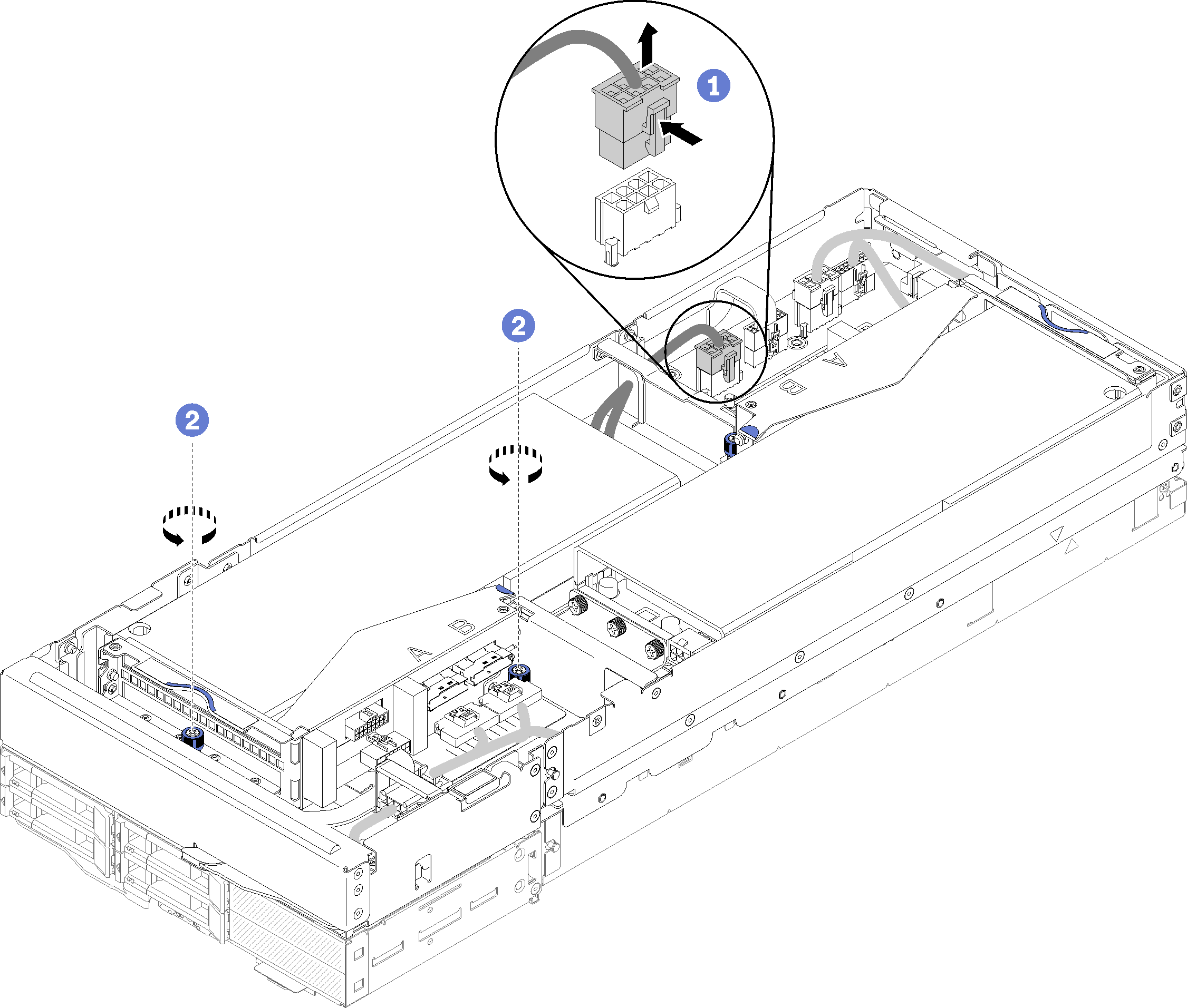
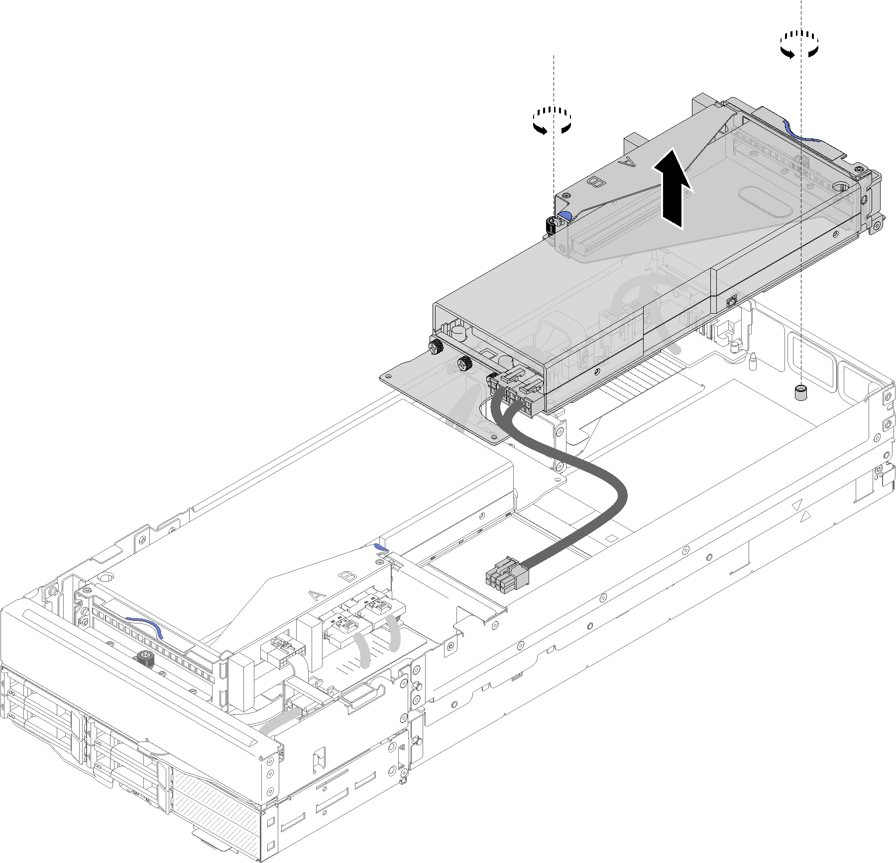
- Press on the latch of the auxiliary power cable connector to disengage and disconnect it from the expansion node.Figure 2. Disconnecting the auxiliary power cable and loosening captive screws of the front riser assembly
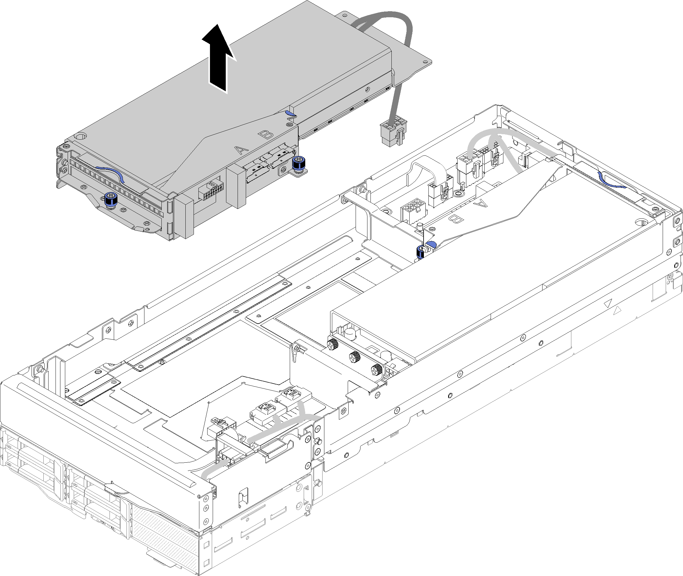
- Remove the front riser assembly from the expansion node.Figure 3. Removing the front riser assembly from the expansion node
Remove the rear PCIe riser assembly
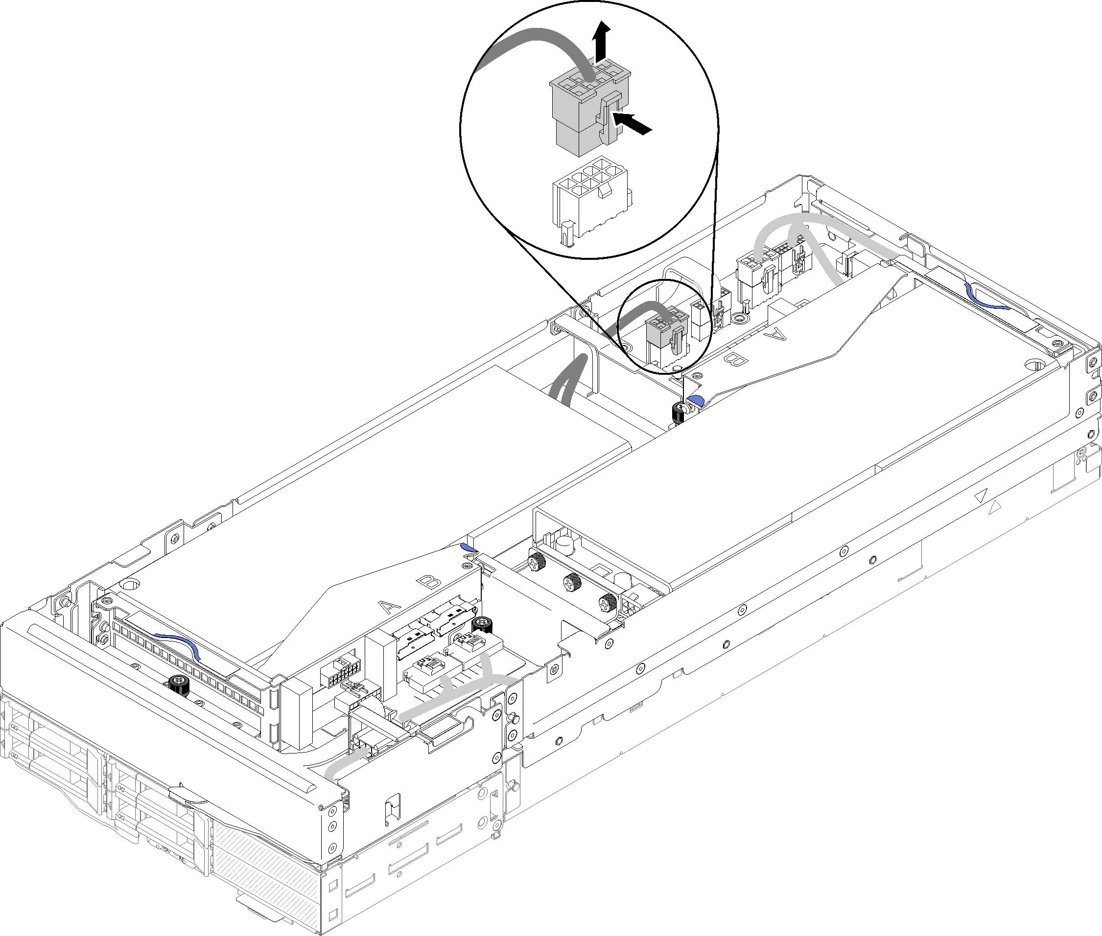
- If the front riser assembly is installed in the expansion node, disconnect the front riser auxiliary power cable from the expansion node.Figure 4. Disconnecting the front riser auxiliary power cable
- Disconnect PCIe#1-A, PCIe#2-B and the riser miscellaneous cable from the rear riser assembly.Figure 5. Disconnecting PCIe#1-A, PCIe#2-B, rear riser miscellaneous and auxiliary power cable
- Loosen the two captive screws, and remove the rear riser assembly from the expansion node.Figure 6. Removing the rear riser assembly from the expansion node
After removing the PCIe riser assembly from the expansion node, complete the following steps:
If only one adapter is installed and no new adapter is to be installed, make sure the adapter is installed in the rear riser slot. If not, complete the following steps:
Remove the front riser assembly (see Remove the front PCIe riser assembly).
Keep the adapter in the riser assembly, and install it to the rear riser slot (see Install the rear PCIe riser assembly).
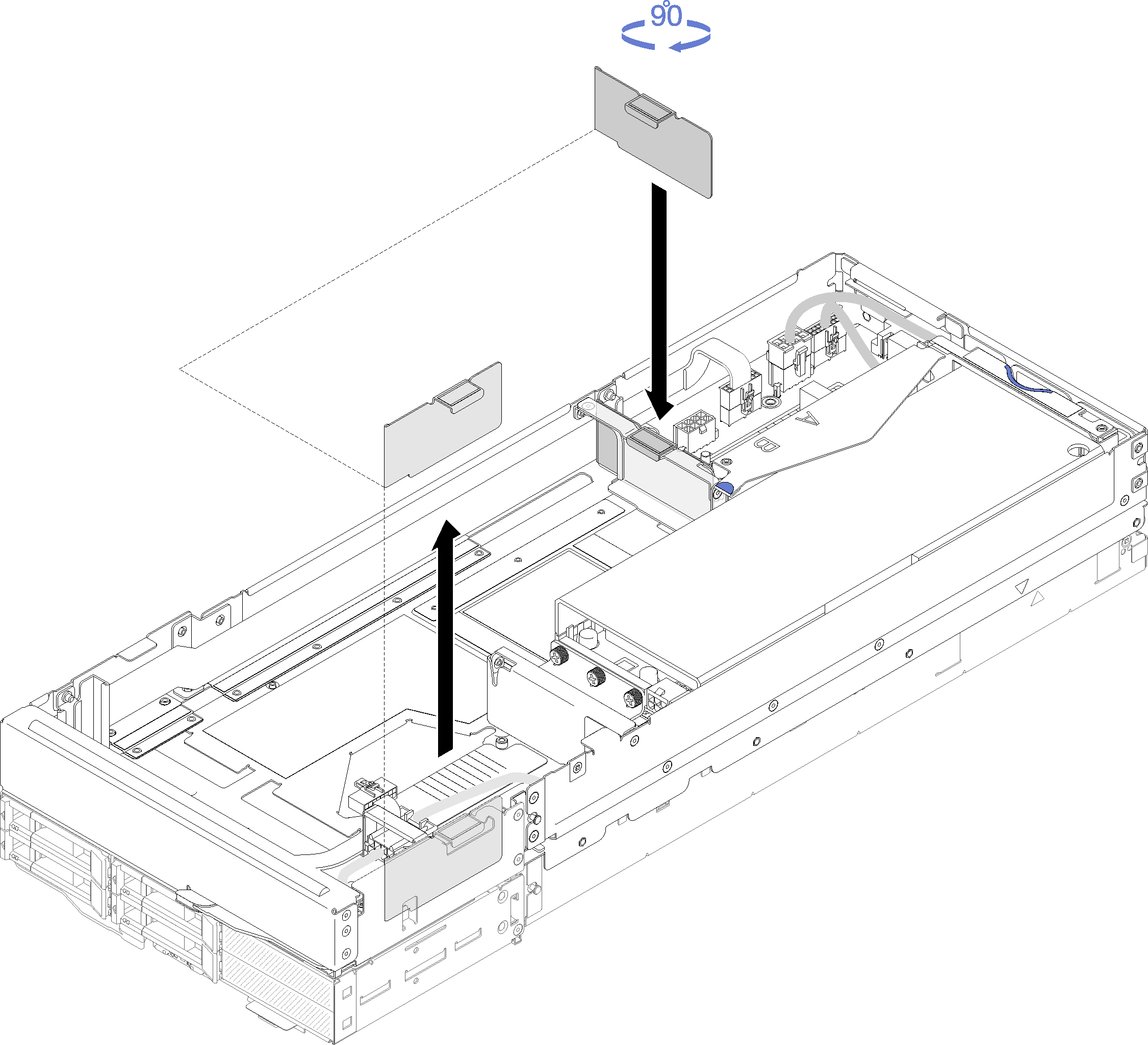
- Remove the airflow filler from the side of the expansion node, and place it into the gap by the front riser slot.Figure 7. Airflow filler installation
- Tighten the two captive screw on the riser cage and secure it to the expansion node for future use.Figure 8. Front riser cage installation
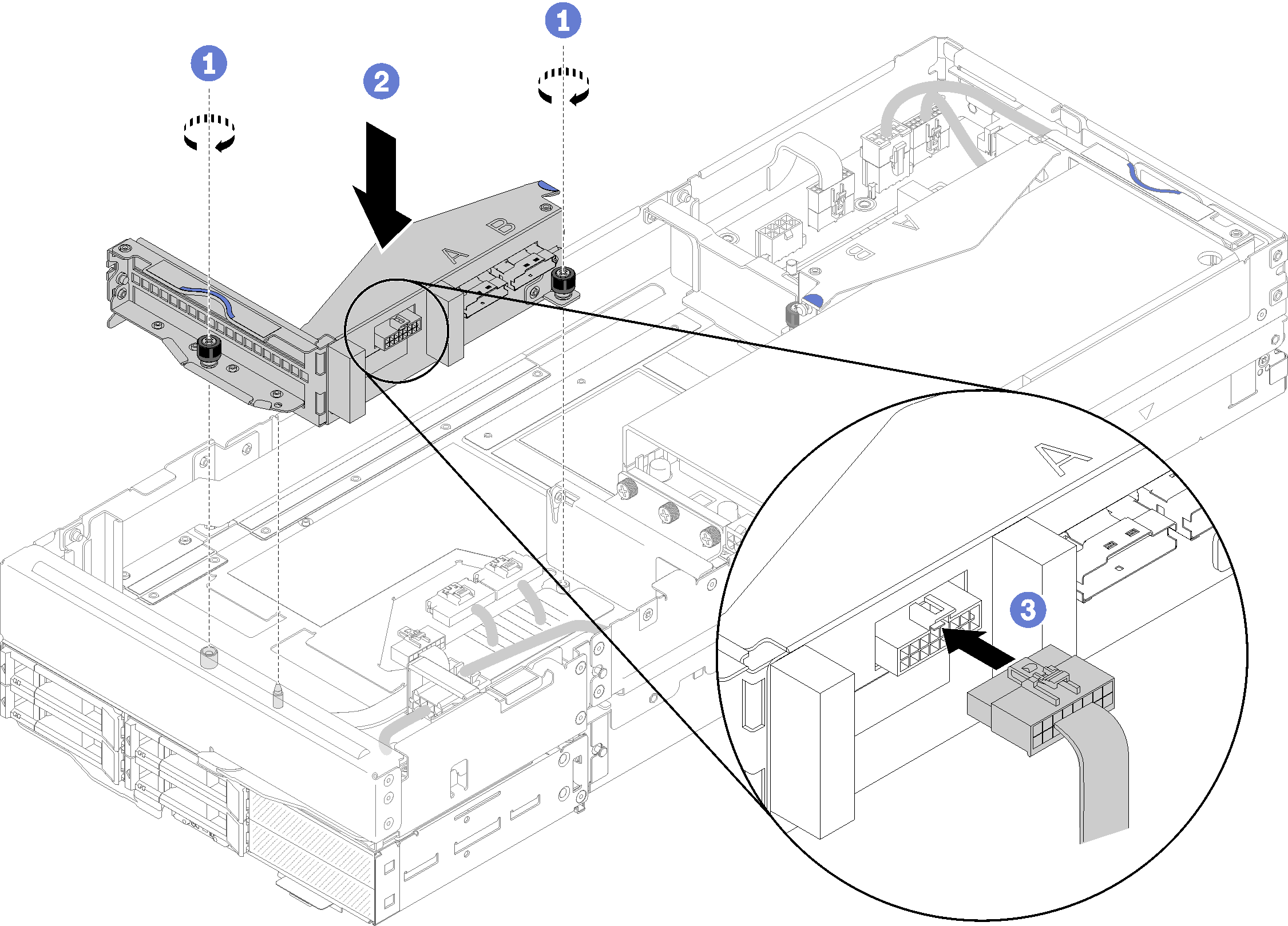
Connect the front riser miscellaneous cable to the riser cage.
Install the rear cable cover (see Install the rear cable cover).
Install the PCIe expansion node assembly into the enclosure (see Install the compute-expansion node assembly into the enclosure).
Power on the compute node.
Demo video