Install a PCIe riser assembly into the PCIe expansion node assembly
Use this information to install a PCIe riser assembly into the compute-expansion node assembly.
- Read the following section(s) to ensure that you work safely.
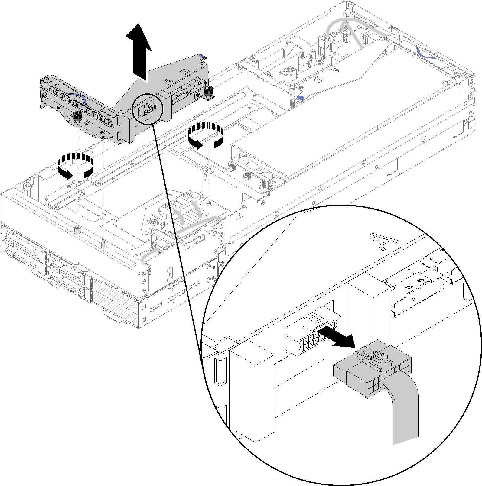
- If no adapter is installed in the riser cage, disconnect the front riser miscellaneous cable first if you are removing the front riser cage, and loosen the two captive screws to remove the riser cage from the expansion node; then, install an adapter into the riser cage (see Install a PCIe adapter into the riser cage) .Figure 1. Riser cage removal
If you are installing a new adapter in addition to an existing one, remove the airflow filler from the gap by the front riser slot, and place it into the gap on the side of the expansion node as illustrated.
Figure 2. Airflow filler removal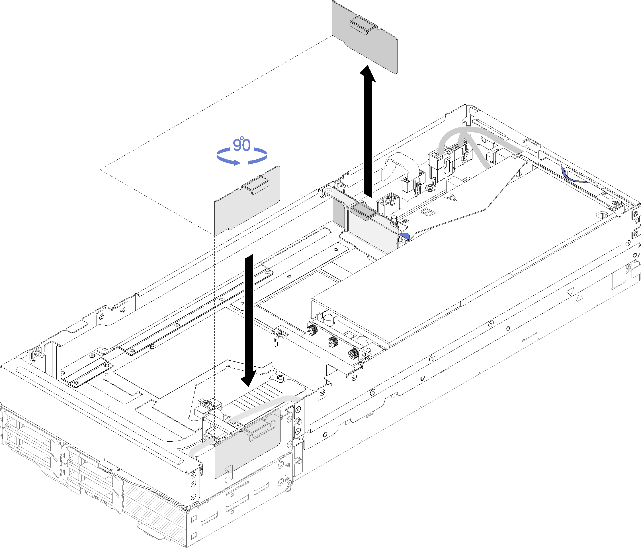
Complete the following steps to install a PCIe riser assembly into the PCIe expansion node assembly.
Always start the installation from the rear riser slot (go to Install the rear PCIe riser assembly).
When only one adapter is to be installed, make sure the adapter is install in the rear riser slot, and place the airflow filler into the gap by the front riser slot.
Install the front PCIe riser assembly
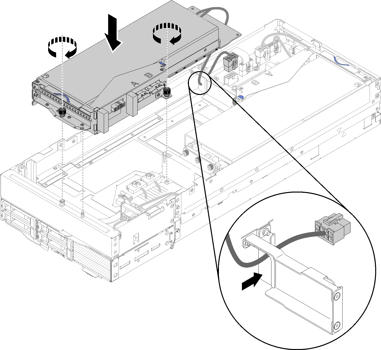
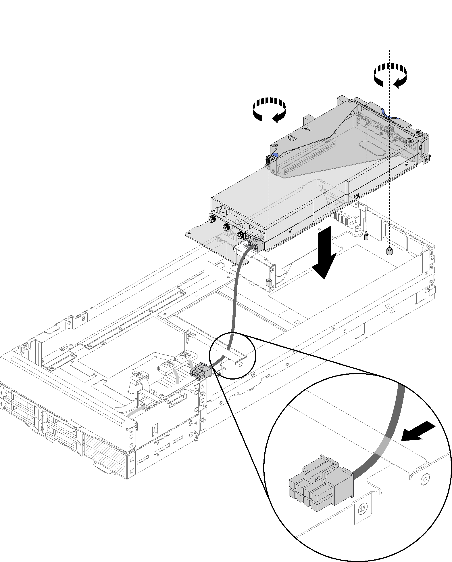
- Pass the auxiliary power cable through the narrow window as illustrated; then, align the riser assembly to the guide pins on the expansion node, and lower it until it stops.Figure 3. Installing the front riser assembly into the expansion node
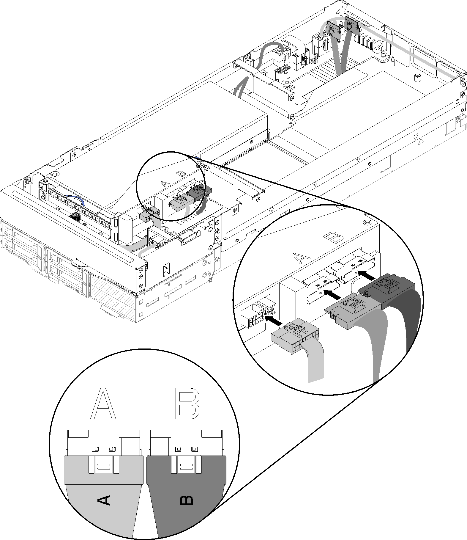
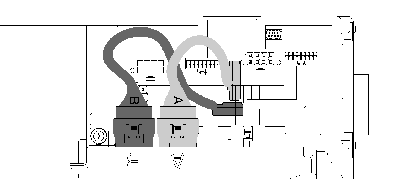
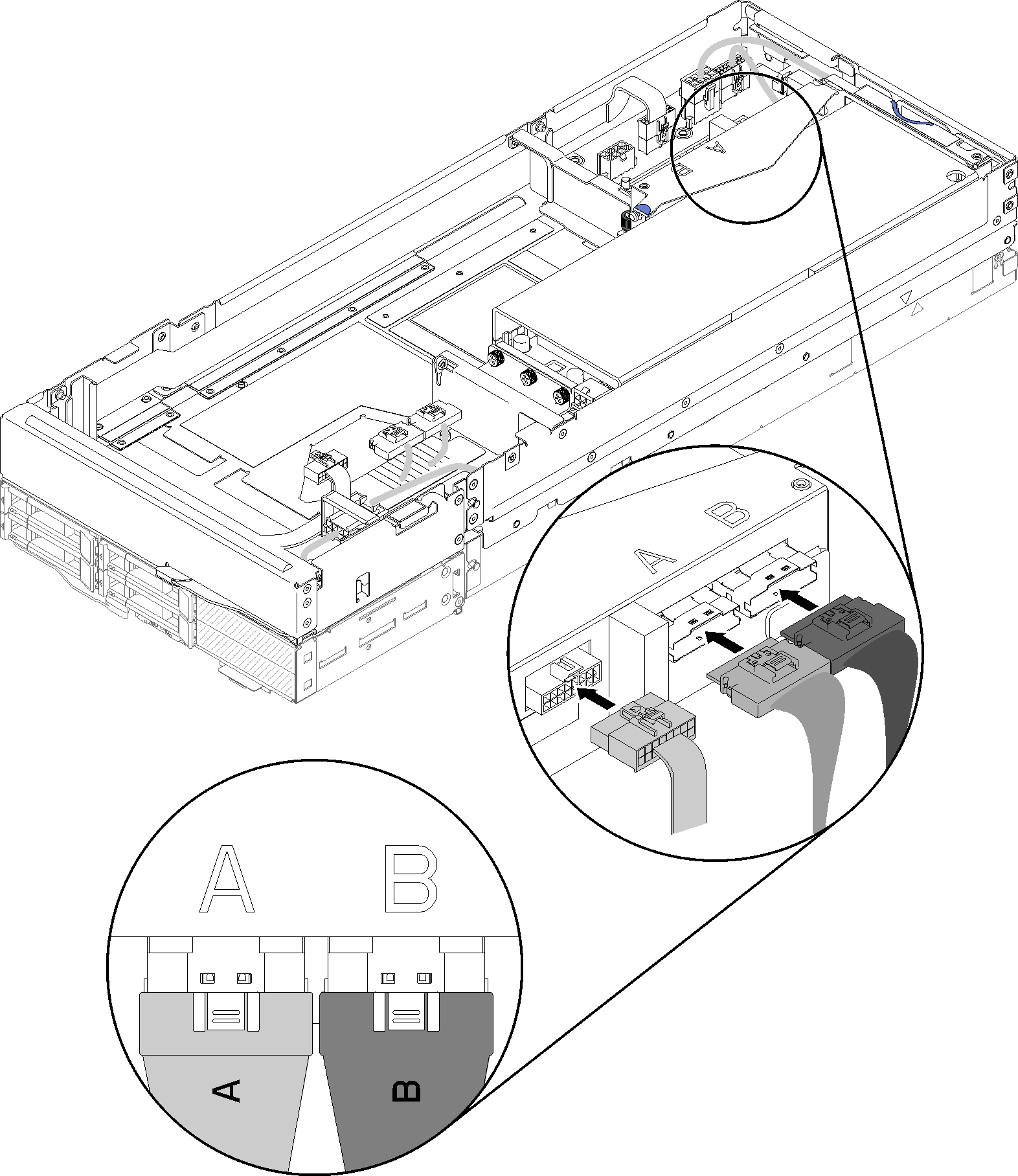
- Connect PCIe#3-A cable to the riser connector labeled “A.”Figure 4. Connecting PCIe#3-A, PCIe#4-B and the riser miscellaneous cable to the front riser assembly
- Connect the auxiliary power cable to the expansion node.Figure 5. Connecting the auxiliary power cable to the expansion node
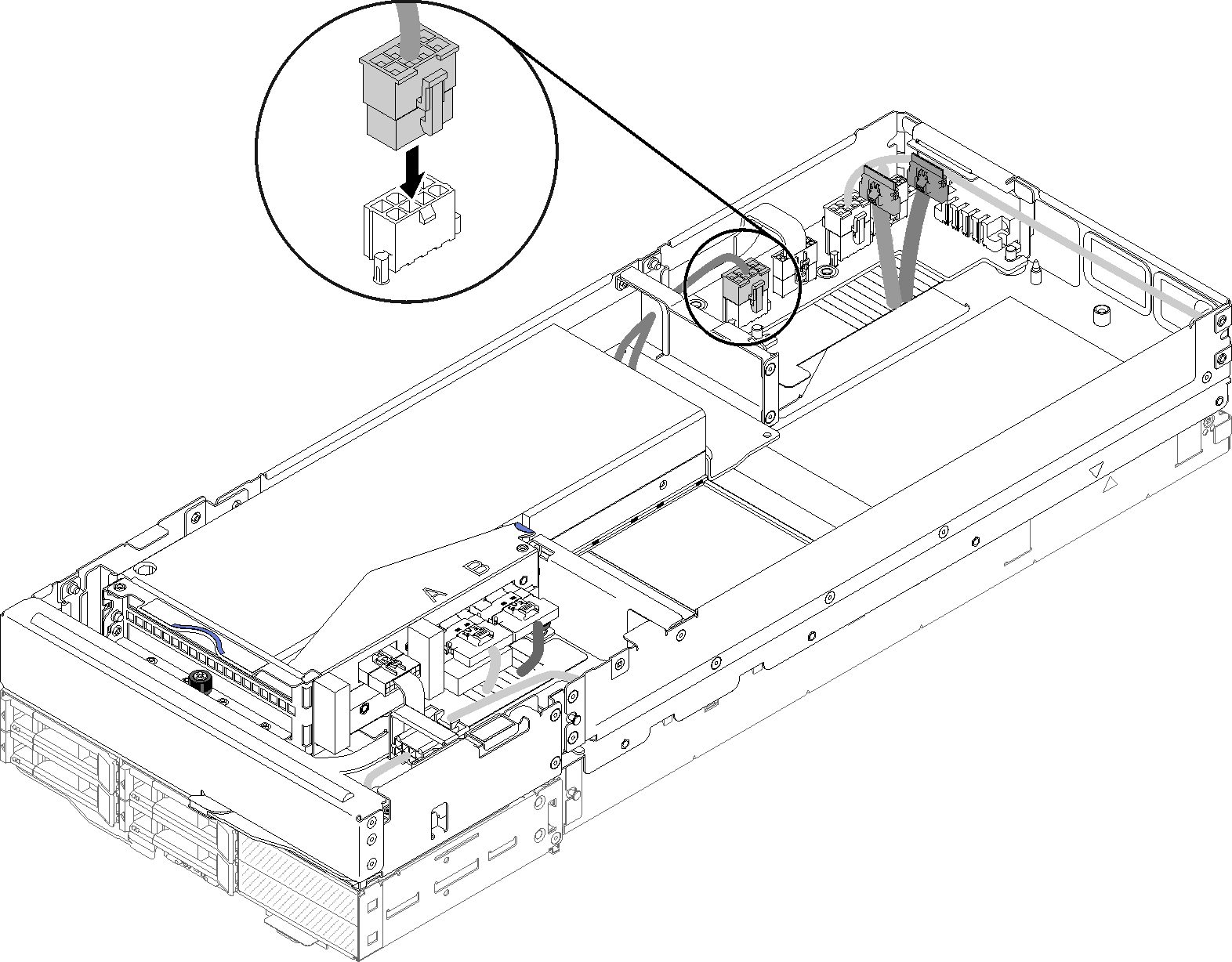
Install the rear PCIe riser assembly
- Pass the auxiliary power cable through the narrow window as illustrated; then, align the riser assembly to the guide pins on the expansion node, and lower it until it stops.Figure 6. Installing the rear riser assembly into the expansion node
- Connect the auxiliary power cable to the expansion node.Figure 7. Connecting the auxiliary power cable to the expansion node
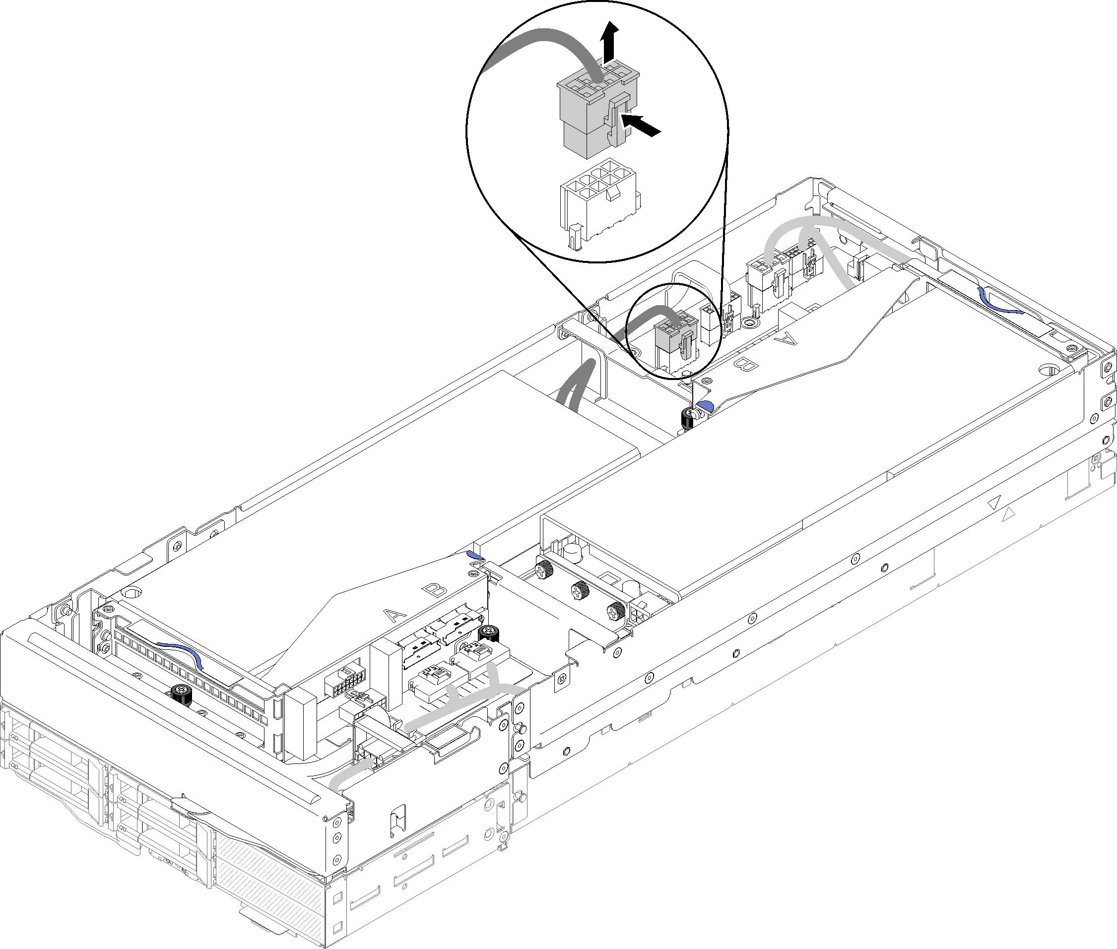
- If the front riser assembly is installed in the expansion node, disconnect the front riser auxiliary power cable from the expansion node.Figure 8. Disconnecting the front riser auxiliary power cable
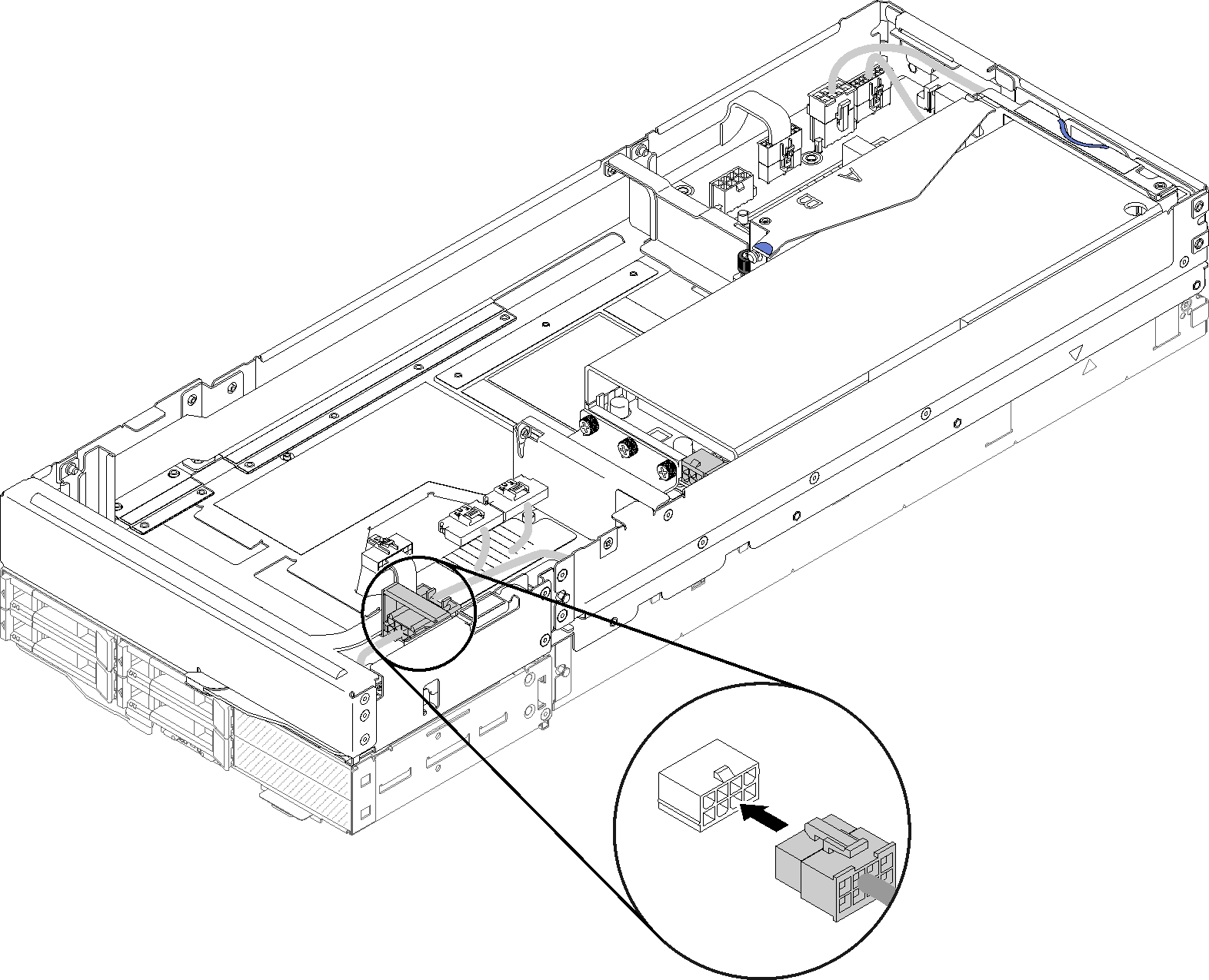
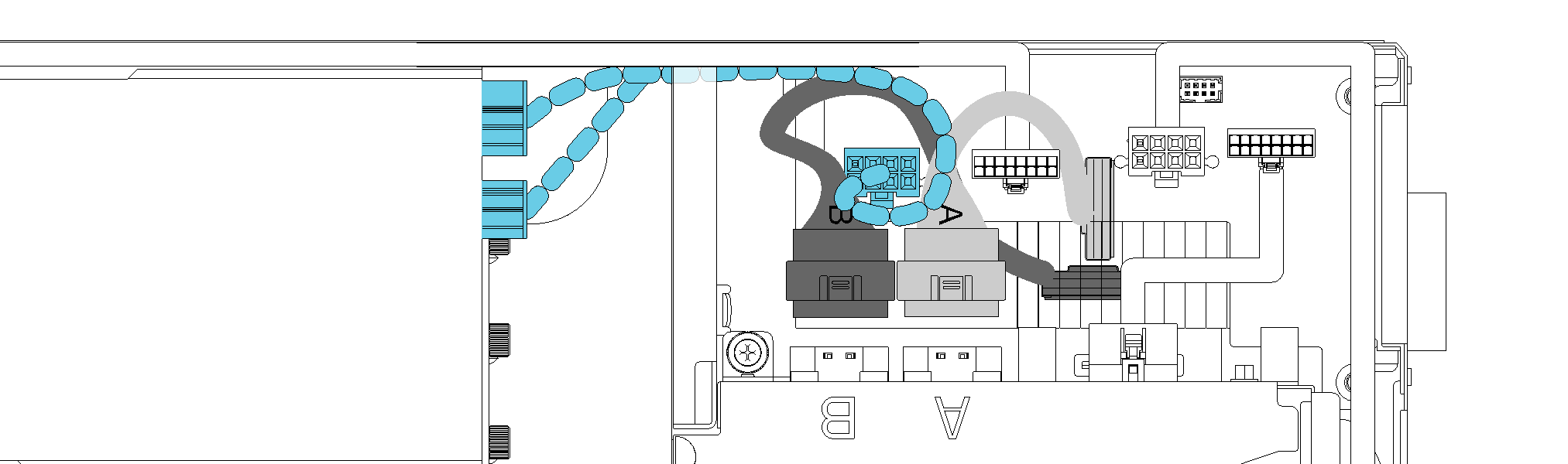
- Route PCIe#2-B cable between the two front riser power connectors, and connect it to the riser connector labeled “B.”Figure 9. Routing PCIe#1-A and PCIe#2-B cable
- Connect the riser miscellaneous cable to the riser assembly.Figure 10. Connecting PCIe#1-A, PCIe#2-B and the riser miscellaneous cable to the rear riser assembly
- If the front riser auxiliary power cable has been disconnected earlier, loop it back into the gap between the two front riser power connectors, route it above PCIe#2-B cable, and reconnect it to the expansion node. Figure 11. Routing the front riser auxiliary power cable to the expansion node
After you install the PCIe riser assembly into the compute-expansion node assembly, complete the following steps:
If only one adapter is installed, remove the airflow filler from the side of the expansion node, and place it into the gap by the front riser slot.
Figure 12. Air filler installation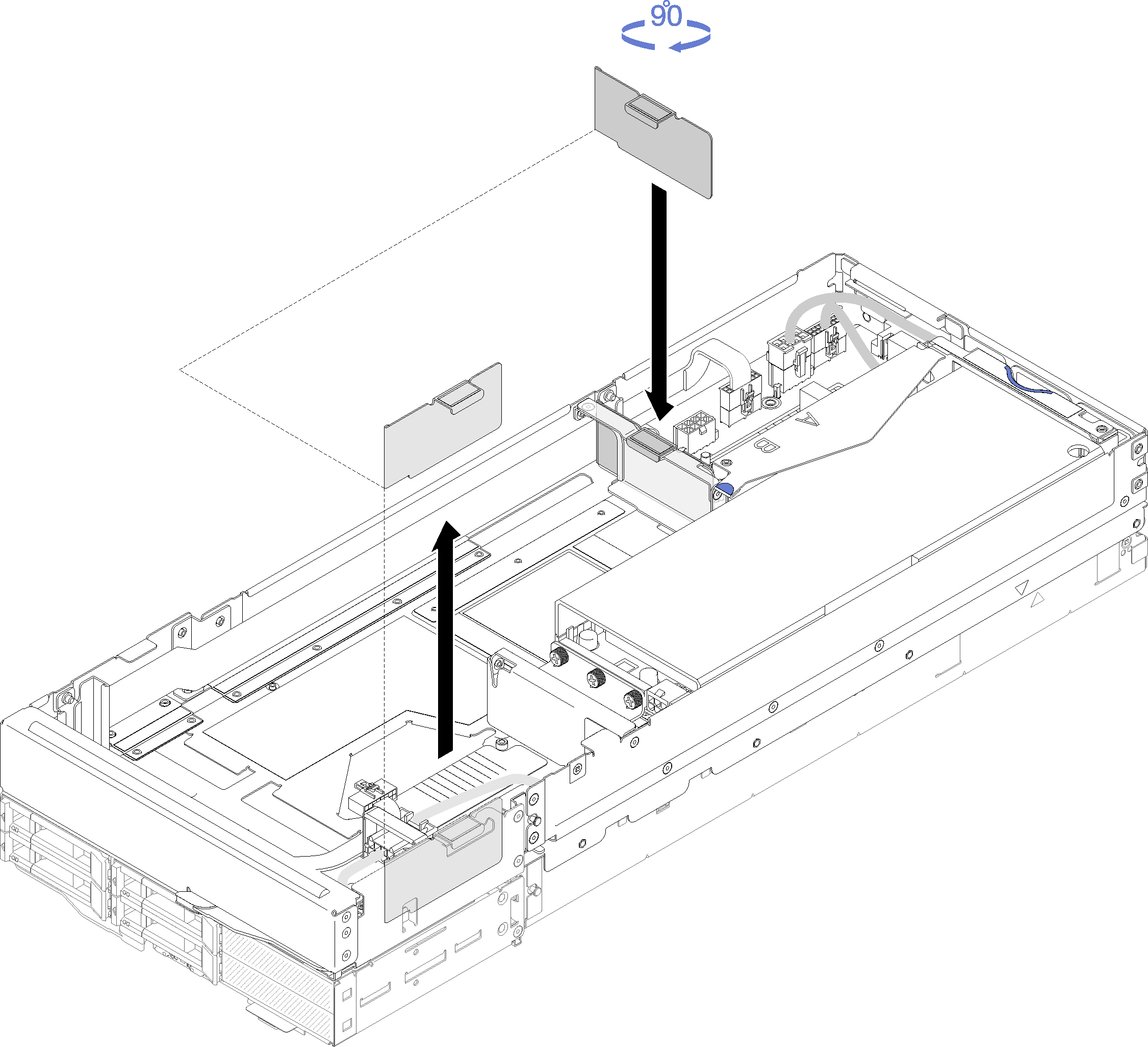
Install the rear cable cover (see Install the rear cable cover).
Install the PCIe expansion node assembly into the enclosure (see Install the compute-expansion node assembly into the enclosure).
Turn on all compute nodes.
Demo video