Remove a drive bay blank
Use this procedure to remove a drive bay blank.
Before removing a drive bay blank:
- Read the following section(s) to ensure that you work safely.
- Remove the compute node (see Remove a compute node from the enclosure).
- Remove the compute node cover (see Remove the compute node cover).
Complete the following steps to remove a drive bay blank.
- Push the blank from the rear of the node (close to the backplane) towards the front to disengage it from the backplane.
For the drive bay blank in drive bay 0 and 1
Figure 1. Drive bay blank (in drive bay 0 and 1) removal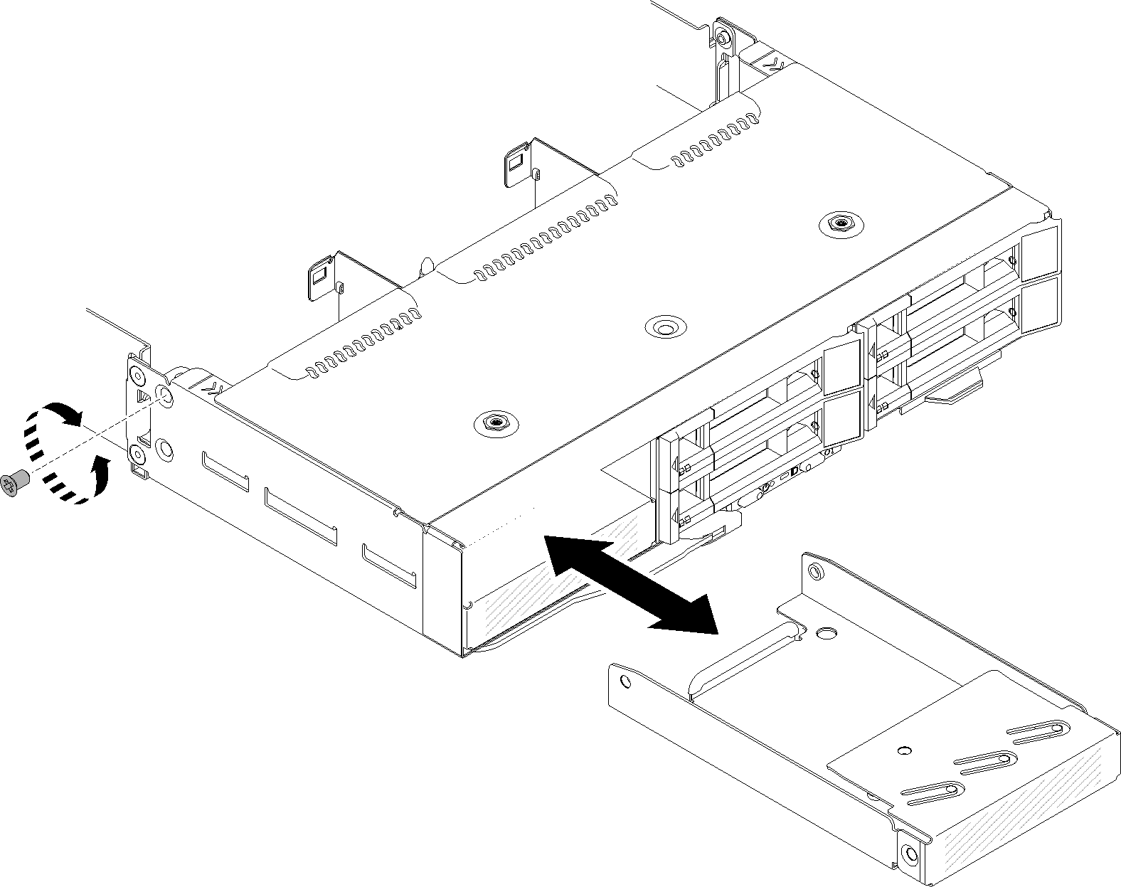
For the drive bay blank in drive bay 2
Figure 2. Drive bay blank (in drive bay 2) removal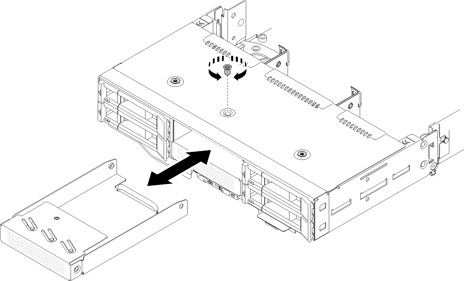
For the drive bay blank in drive bay 3
NoteThe following illustration shows the underside of the node.Figure 3. Drive bay blank (in drive bay 3) removal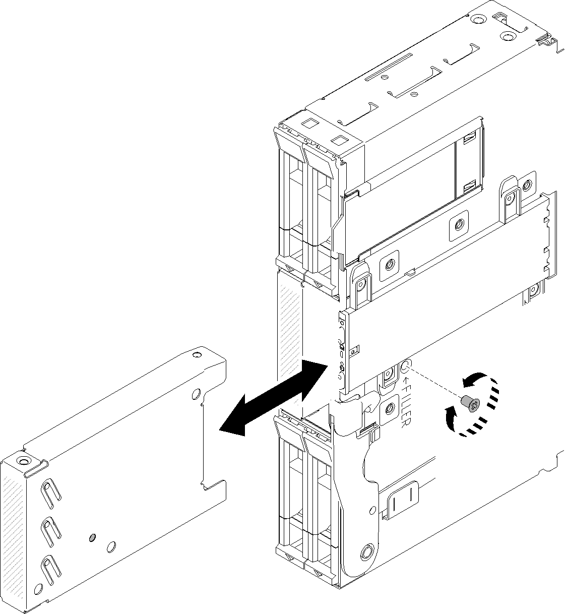
For the drive bay blank in drive bay 4 and 5
Figure 4. Drive bay blank (in drive bay 4 and 5) removal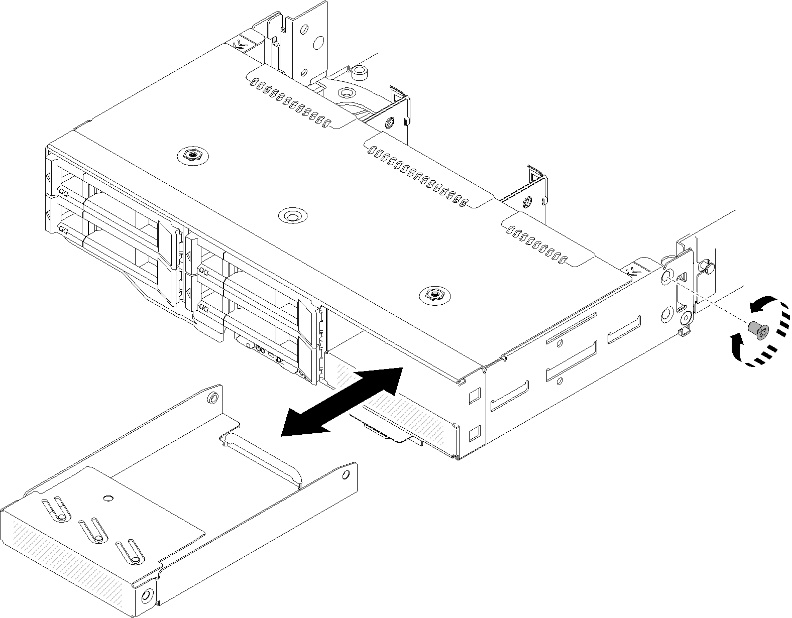
If you are instructed to return the component or optional device, follow all packaging instructions, and use any packaging materials for shipping that are supplied to you.
Give documentation feedback