Enclosure
The following illustration shows the controls, LEDs, and connectors on the front of the enclosure.
Note
The illustrations in this document might differ slightly from your hardware.
For proper cooling, every empty node bay has to be installed with either a node or a node filler before the solution is powered on.
The enclosure supports the following configurations:
Up to four compute nodes.
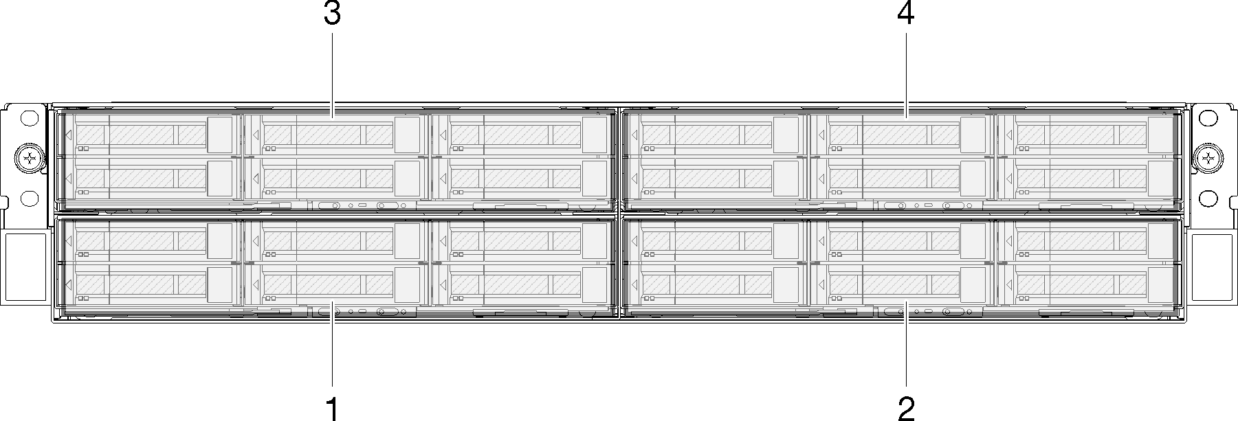
The following illustration shows the node bays in the enclosure.
Figure 1. Enclosure front view with compute nodes and node bay numbering
Up to two PCIe expansion node assemblies.
Figure 2. Compute-expansion node assembly
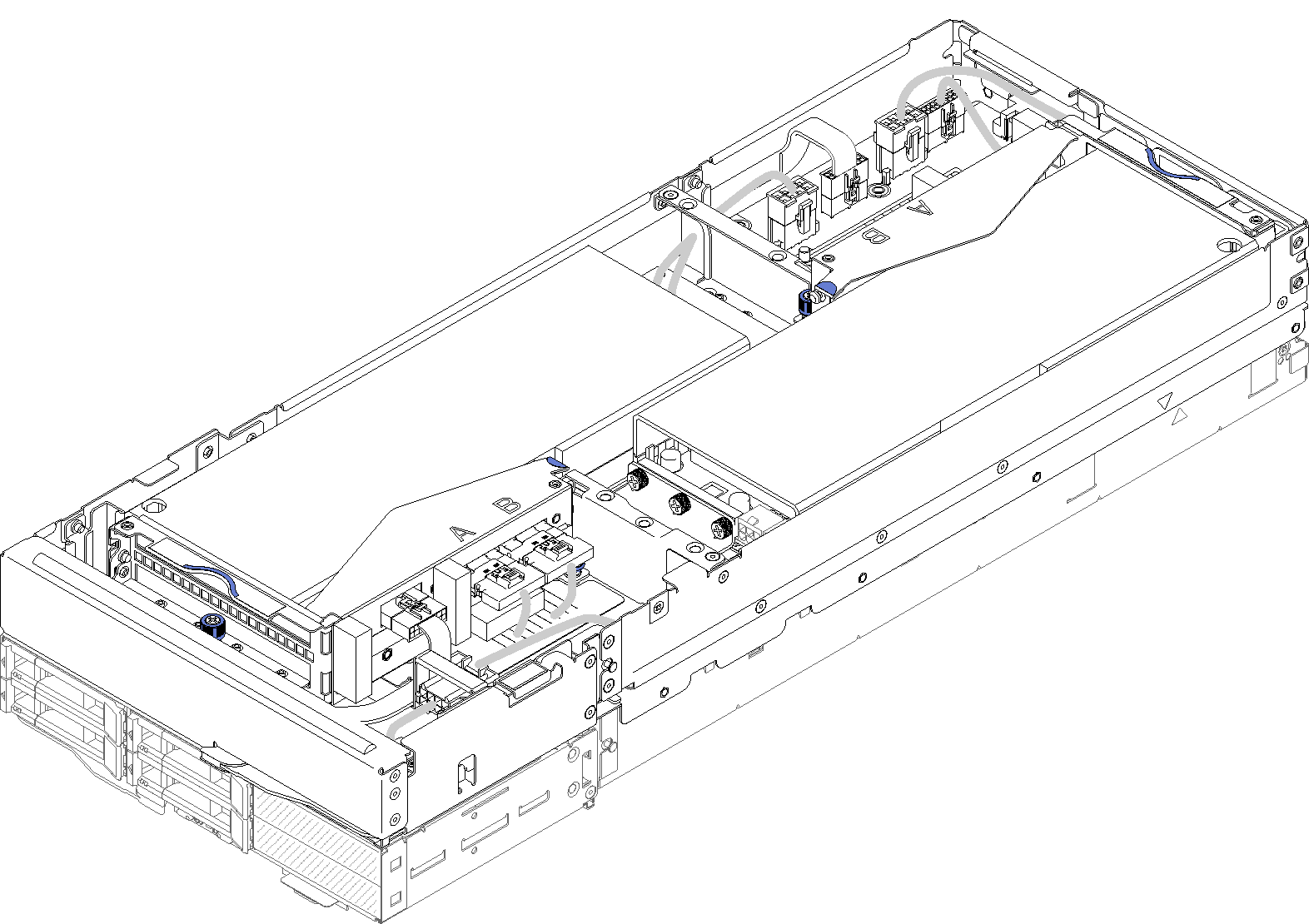
A compute-expansion node assembly consists of a PCIe expansion node and a compute node, to which the expansion node is installed. The node assembly takes two vertically adjacent node bays in an enclosure. See PCIe expansion node specifications for detailed PCIe expansion node requirements.Note
Do not mix a compute-expansion node assembly with compute nodes in the same enclosure. When a a compute-expansion node assembly is installed in an enclosure, fill the other two node bays with either two node fillers or another unit of compute-expansion node assembly.
Figure 3. Enclosure front view with PCIe expansion node assemblies
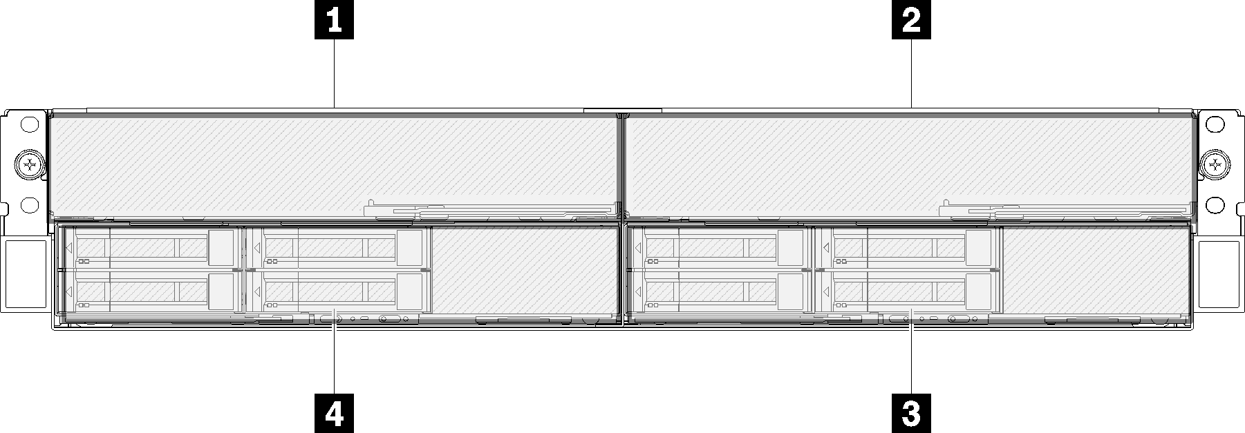
| 1 PCIe expansion node | 3 Compute node |
| 2 PCIe expansion node | 4 Compute node |
Give documentation feedback