Node operator panel
The following illustration shows the controls and LEDs on the node operator panel.
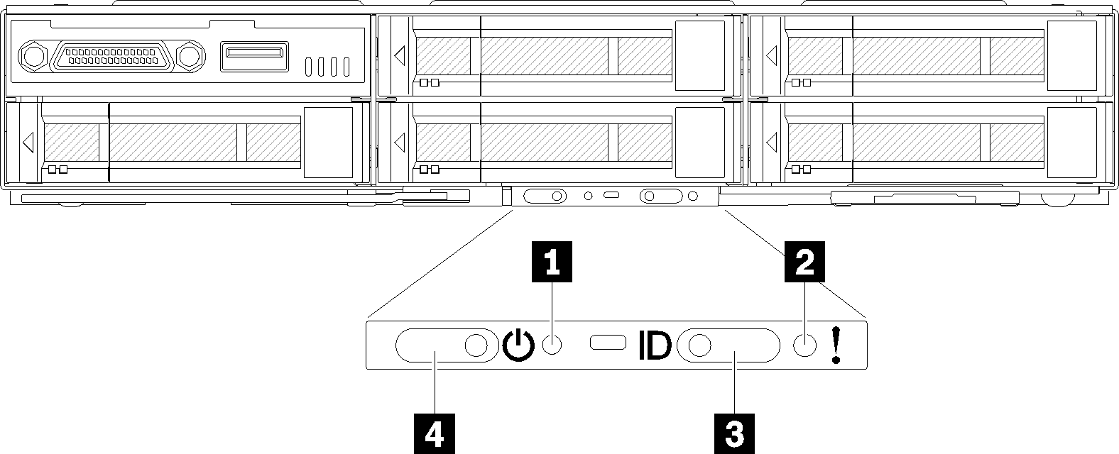
| 1 NMI pinhole | 3 Identification button/LED |
| 2 System error LED | 4 Power button/LED |
1 NMI pinhole: Insert the tip of a straightened paper clip into this pinhole to force a non-maskable interrupt (NMI) upon the node, and consequent memory dump would take place. Only use this function while advised by Lenovo support representative.
2 System error LED: When this LED (yellow) is lit, it indicates that at least one system error has occurred. Check the event log for additional information.
3 Identification button/LED: This LED (blue) serves to visually locate the compute node, and can be turned on with pressing on the identification button or the following commands.
Command to turn Identification LED on:
ipmitool.exe -I lanplus -H <XCC’s IP> -U USERID -P PASSW0RD raw 0x3a 0x08 0x01 0x01
Command to turn Identification LED off:
ipmitool.exe -I lanplus -H <XCC’s IP> -U USERID -P PASSW0RD raw 0x3a 0x08 0x01 0x00
NoteDefault XCC’s IP address is 192.168.70.125
The behavior of this LED is determined by the SMM ID LED when SMM ID LED is turned on or blinking. For the exact location of SMM ID LED, see System Management Module (SMM).
Table 2. Different SMM ID LED modes and Node ID LED behavior SMM identification LED Node identification LEDs Off All node ID LEDs are turned off when this mode is activated. Afterwards, SMM ID LED enters accept mode, while node ID LEDs determine the behavior of SMM ID LEDs (see Enclosure rear overview for more information). On All the node ID LEDs are on except the blinking ones, which remain blinking. Blink All the node ID LEDs are blinking regardless of previous status.
Flashing rapidly: The LED flashes rapidly for the following reasons:
The node has been installed in an enclosure. When you install the compute node, the LED flashes rapidly for up to 90 seconds while the Lenovo XClarity Controller in the node is initializing.
The power source is not sufficient to turn on the node.
The Lenovo XClarity Controller in the node is not communicating with the System Management Module.
Flashing slowly: The node is connected to the power through the enclosure and ready to turn on.
Lit continuously: The node is connected to the power through the enclosure.
Not lit continuously: No power on node.