Compute node
The following illustration shows the controls, LEDs, and connectors on the front of the compute node.
Six 2.5-inch drive configuration
See the following illustration for components, connectors and drive bay numbering in six 2.5-inch drive configuration.
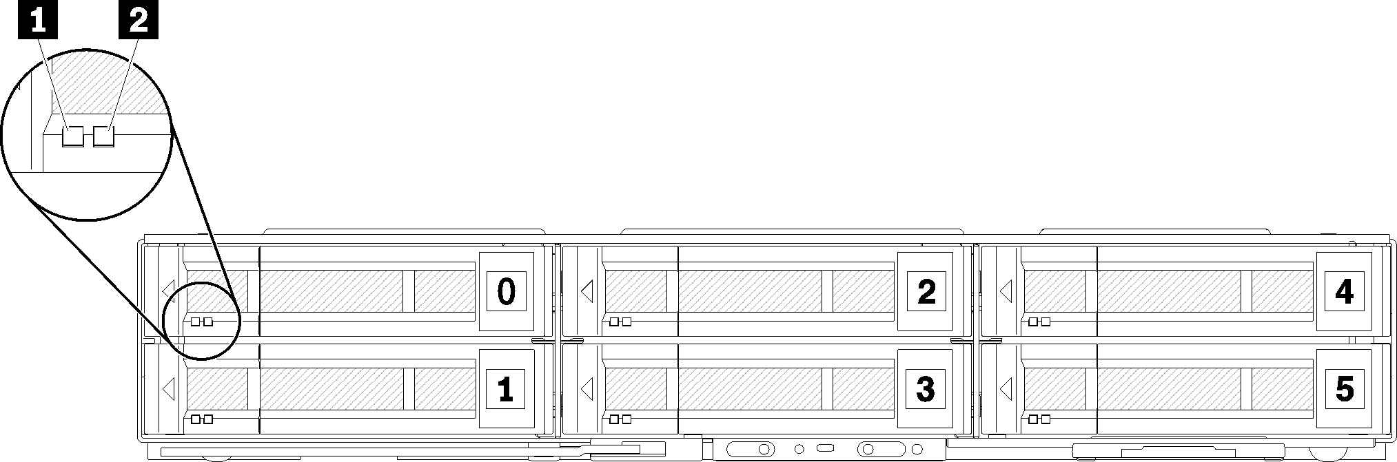
| 1 Activity LED (green) | 2 Status LED (yellow) |
Drive LEDs:
When this LED is flashing, it indicates that the drive is actively reading or writing data.
For SAS and SATA drives, this LED is off when the drive is powered but not active.
For NVMe (PCIe) SSDs, this LED is on solid when the drive is powered but not active.
When the yellow LED is lit continuously, it indicates that an error has occurred with the associated drive. The LED turns off only after the error is corrected. You can check event logs to determine the source of the condition.
When the yellow LED flashes slowly, it indicates that the associated drive is being rebuilt.
When the yellow LED flashes rapidly, it indicates that the associated drive is being located.
Five 2.5-inch drive configuration with KVM breakout module
See the following illustration for components, connectors and drive bay numbering in five 2.5-inch drive configuration with KVM breakout module.
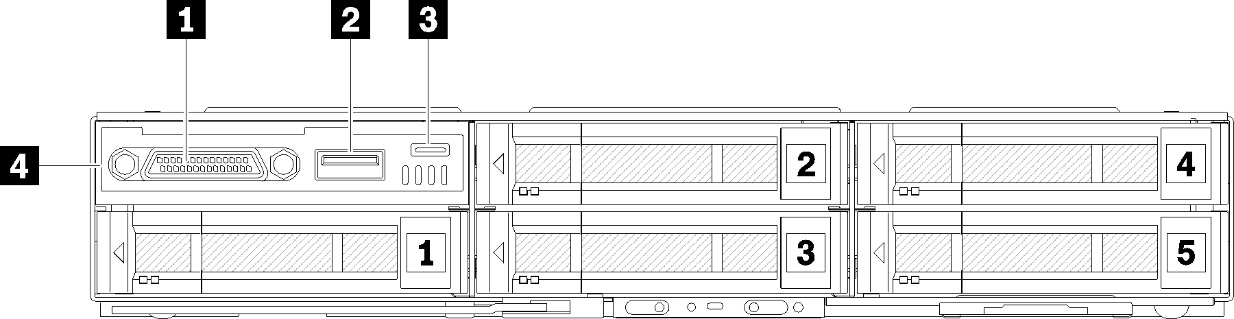
| 1 KVM connector | 3 Micro USB connector for Lenovo XClarity Controller management |
| 2 USB 3.0 connector | 4 KVM breakout module |
KVM breakout module comes with the following connectors:
1 KVM connector: Connect the console breakout cable to this connector (see KVM breakout cable more information).
2 USB 3.0 connector: Connect a USB device to this USB 3.0 connector.
3 Micro USB connector for Lenovo XClarity Controller management: The connector provides direct access to Lenovo XClarity Controller by allowing you to connect a mobile device to the system and manage it with Lenovo XClarity Controller. For more details, see Lenovo XClarity Controller portal page and Lenovo XClarity Administrator online documentation for more information.
Ensure that you use a high-quality OTG cable or a high-quality converter when connecting a mobile device. Be aware that some cables that are supplied with mobile devices are only for charging purposes.
Once a mobile device is connected, it indicates it is ready to use and no further action is required.
Four 2.5-inch drive configuration with KVM breakout module
See the following illustration for components, connectors and drive bay numbering in four 2.5-inch drive configuration with KVM breakout module.
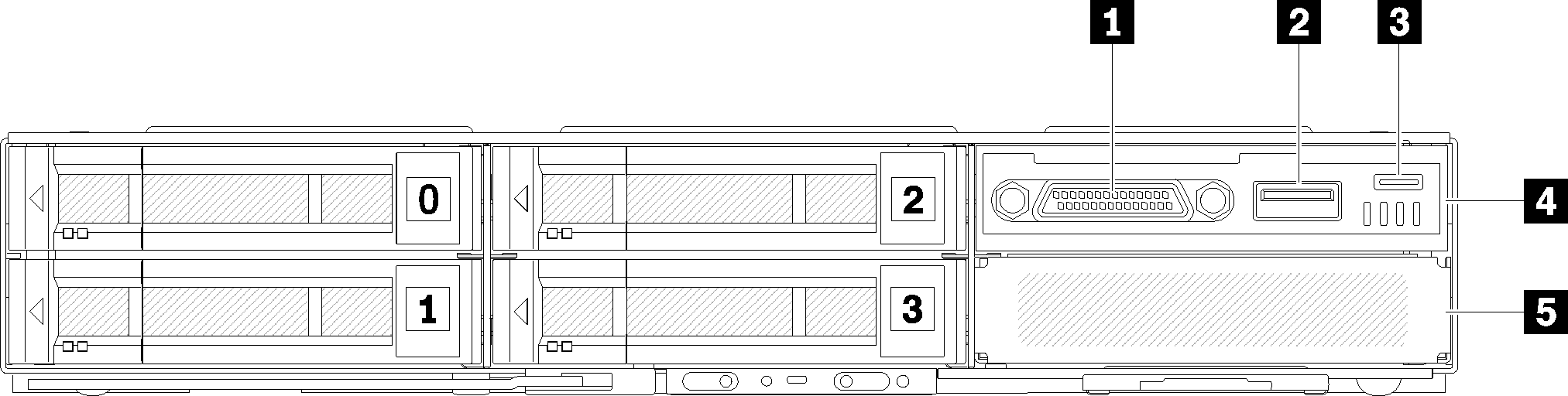
| 1 KVM connector | 4 KVM breakout module |
| 2 USB 3.0 connector | 5 Drive bay filler |
| 3 Micro USB connector for Lenovo XClarity Controller management |