Rear view
The following illustration shows the connectors and LEDs on the rear of the enclosure.
The following illustration shows the rear view of the entire system.
Shuttle with eight low profile PCIe x8 slots
Figure 1. Rear view - The enclosure with x8 shuttle installed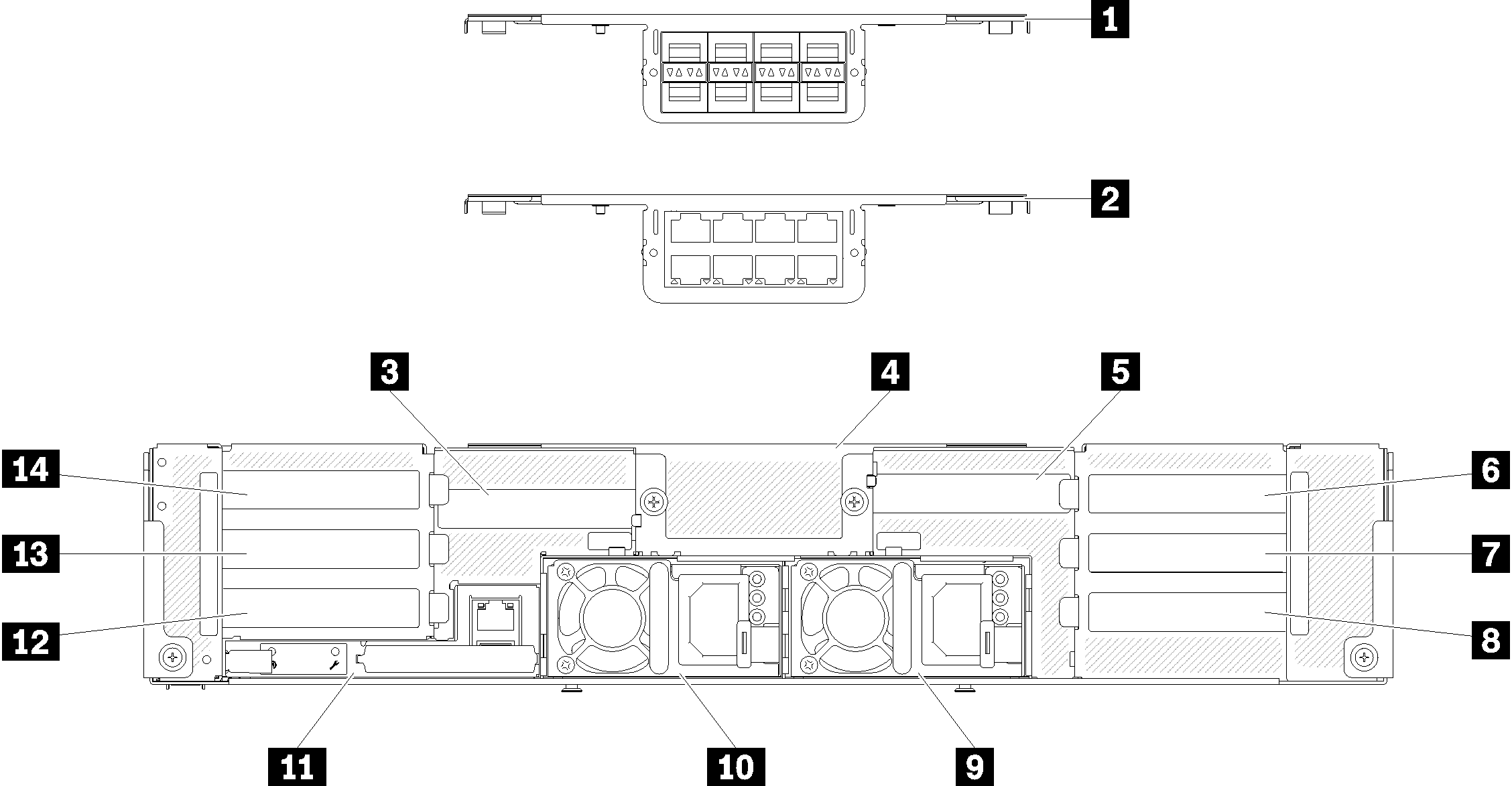
Table 1. Components on x8 shuttle 1 10Gb 8-port EIOM cage (SFP+) 8 PCIe slot 1-B 2 10Gb 8-port EIOM cage (RJ45) 9 Power supply 2 3 PCIe slot 4-B 10 Power supply 1 4 10Gb 8-port EIOM cage filler 11 System Management Module 5 PCIe slot 3-B 12 PCIe slot 2-B 6 PCIe slot 3-A 13 PCIe slot 2-A 7 PCIe slot 1-A 14 PCIe slot 4-A NoteMake sure the power cord is properly connected to every power supply unit installed.Shuttle with four low profile PCIe x16 cassette bays
Figure 2. Rear view - The enclosure with x16 shuttle installed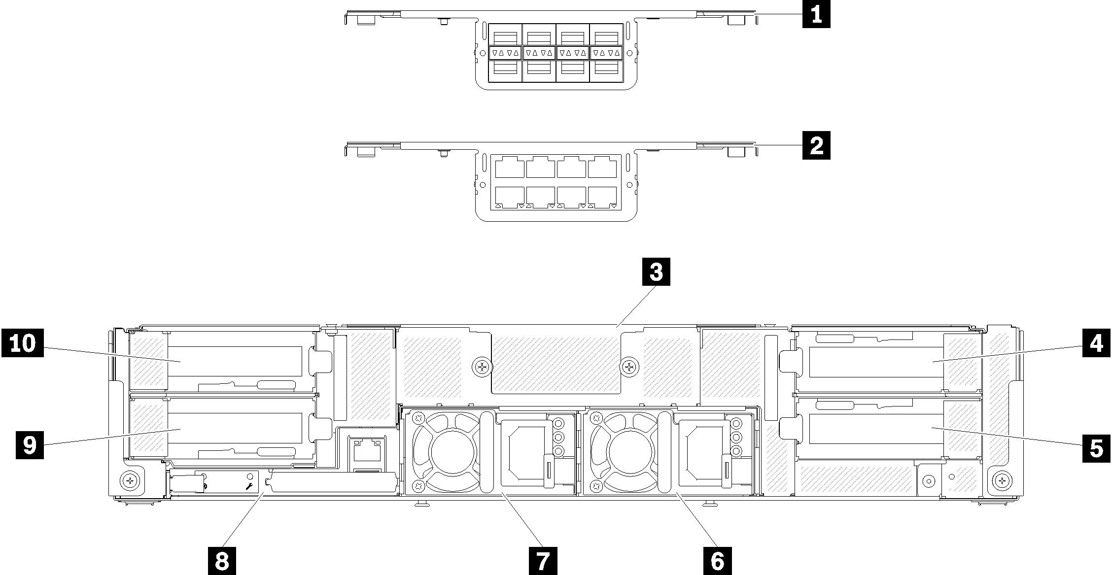
Table 2. Components on x16 shuttle 1 10Gb 8-port EIOM cage (SFP+) 6 Power supply 2 2 10Gb 8-port EIOM cage (RJ45) 7 Power supply 1 3 10Gb 8-port EIOM cage filler 8 System Management Module 4 PCIe slot 3 9 PCIe slot 2 5 PCIe slot 1 10 PCIe slot 4 NoteMake sure the power cord is properly connected to every power supply unit installed.
Give documentation feedback