System Management Module (SMM)
The following section includes information about the connectors and LEDs on the rear of the System Management Module (SMM).
Two types of SMM are supported in this solution. See the following illustrations to discern the type of SMM that you have.
Single Ethernet port SMM
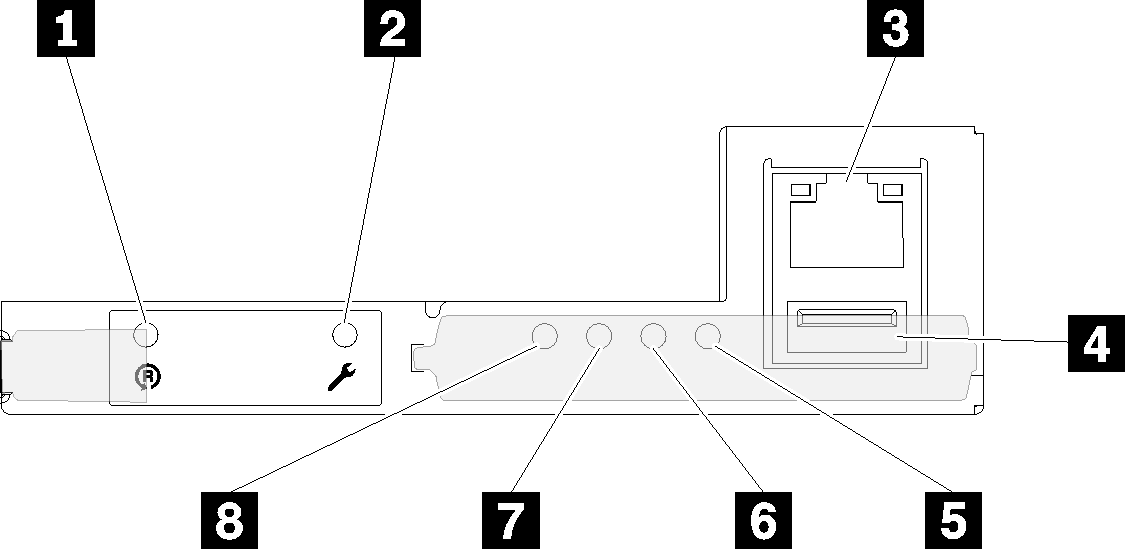
| 1 Reset pinhole | 5 System error LED (yellow) |
| 2 USB port service mode button | 6 Identification LED (blue) |
| 3 Ethernet connector | 7 Status LED (green) |
| 4 USB connector | 8 System power LED (green) |
You can access the dedicated XCC network port of the four nodes via the Ethernet connector on the Single Ethernet port SMM. Go to website and use IP to access XCC. For more details, see System Management Module User's Guide.
The following four LEDs on the single Ethernet port SMM provide information about SMM operating status.
5 System error LED (yellow):
When this LED is lit, it indicates that a system error has occurred. Check the event log for additional information.
6 Identification LED (blue):
Command to turn Identification LED on:
ipmitool.exe -I lanplus -H <SMM’s IP> -U USERID -P PASSW0RD raw 0x32 0x97 0x01 0x01
Command to turn Identification LED off:
ipmitool.exe -I lanplus -H <SMM’s IP> -U USERID -P PASSW0RD raw 0x32 0x97 0x01 0x00
NoteThe default SMM IP address is 192.168.70.100
7 Status LED (green):
Continuously on: the SMM has encountered one or more problems.
Off:
when the enclosure power is on, it indicates the SMM has encountered one or more problems.Flashing: the SMM is working.
During pre-boot process, the LED flashes rapidly (about four times per second).
When the pre-boot process is completed and the SMM is working correctly, the LED flashes at a slower speed (about once per second).
8 System power LED (green):
When this LED is lit, it indicates that the SMM power is on.
Dual Ethernet port SMM
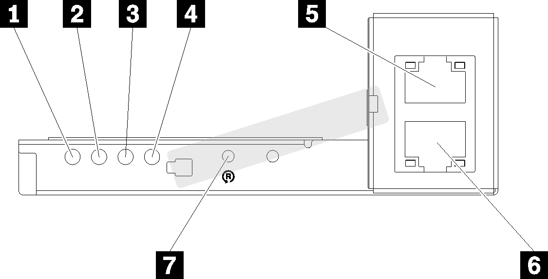
| 1 System power LED (green) | 5 Ethernet connector |
| 2 Status LED (green) | 6 Ethernet connector |
| 3 Identification LED (blue) | 7 Reset pinhole |
| 4 System error LED (yellow) |
You can access the dedicated XCC network port of the four nodes via either of the SMM Ethernet connector. Go to SMM website and use IP to access XCC. For more details, see System Management Module User's Guide.
The following four LEDs on the dual Ethernet port SMM provide information about SMM operating status.
1 System power LED (green):
When this LED is lit, it indicates that the SMM power is on.
2 Status LED (green):
Continuously on: the SMM has encountered one or more problems.
Off:
when the enclosure power is on, it indicates the SMM has encountered one or more problems.Flashing: the SMM is working.
During pre-boot process, the LED flashes rapidly (about four times per second).
When the pre-boot process is completed and the SMM is working correctly, the LED flashes at a slower speed (about once per second).
3 Identification LED (blue):
Command to turn Identification LED on:
ipmitool.exe -I lanplus -H <SMM’s IP> -U USERID -P PASSW0RD raw 0x32 0x97 0x01 0x01
Command to turn Identification LED off:
ipmitool.exe -I lanplus -H <SMM’s IP> -U USERID -P PASSW0RD raw 0x32 0x97 0x01 0x00
NoteThe default SMM IP address is 192.168.70.100
4 System error LED (yellow):
When this LED is lit, it indicates that a system error has occurred. Check the event log for additional information.
For web interface and error messages, see SMM.