Install the Lenovo Processor Neptune® Core Module
Follow the instructions in this section to install the Processor Neptune® Core Module. The procedure must be executed by a trained technician.
About this task
Safety information for leakage sensor module cable
S011

CAUTION
Sharp edges, corners, or joints nearby.
Attention
Read Installation Guidelines and Safety inspection checklist to make sure that you work safely.
- Prevent exposure to static electricity, which might lead to system halt and loss of data, by keeping static-sensitive components in their static-protective packages until installation, and handling these devices with an electrostatic-discharge wrist strap or other grounding system.
Depending on the specific configuration, the hardware might look slightly different from the illustrations in this section.
Prepare the following screwdrivers to ensure you can install and remove the corresponding screws properly.
| Torque screwdriver type list | Screw Type |
|---|---|
| Torx T20 head screwdriver | Torx T20 screw |
Procedure
- Install the processor.
 Slide the processor carrier into the rail frame.
 Push the rail frame down until the blue latches lock into place.
 Close the retention frame.
 Use a Torx T20 screwdriver to tighten the screw.
Figure 1. Installing a processor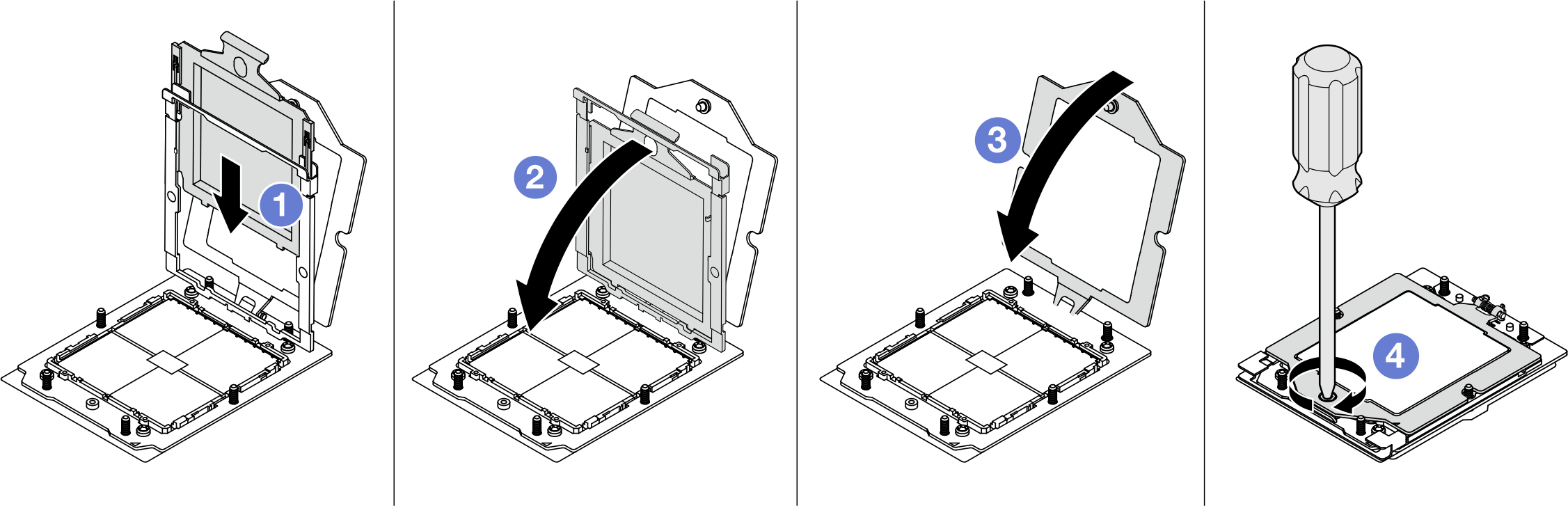
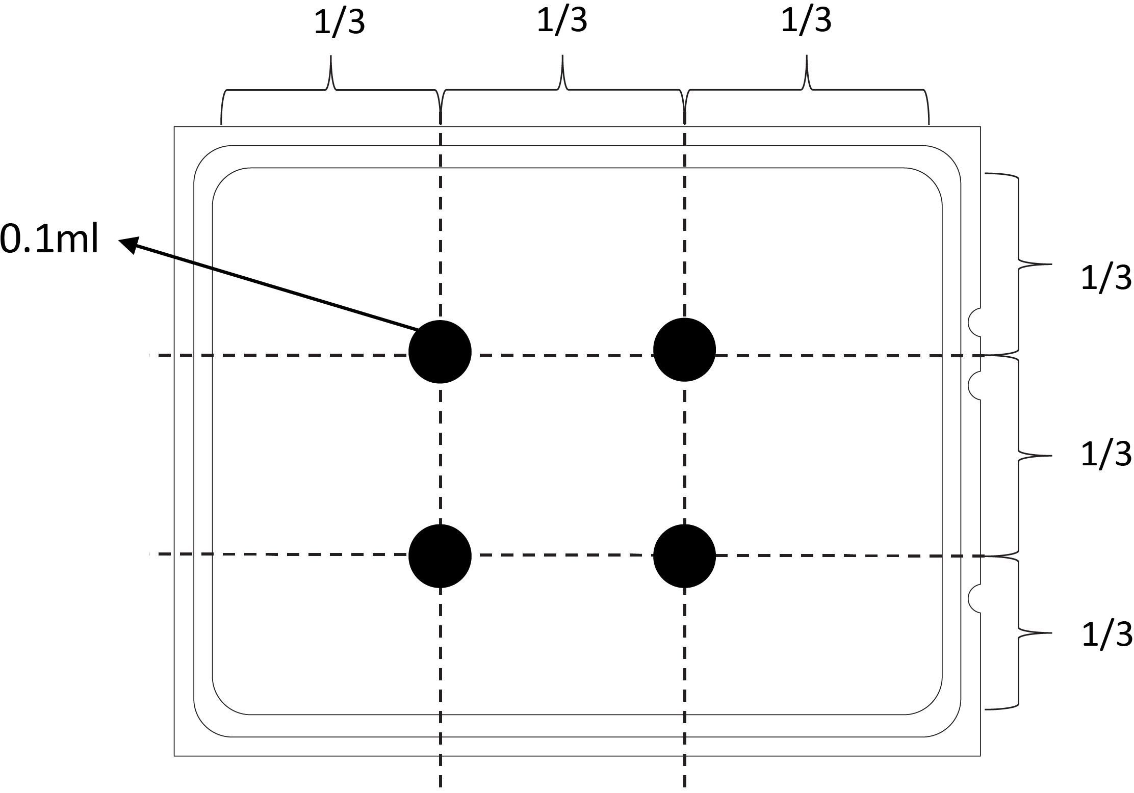
- Apply new thermal grease on the top of the processor with a syringe by forming four uniformly spaced dots, while each dot consists of about 0.1 ml of thermal grease.Figure 2. Applying thermal grease
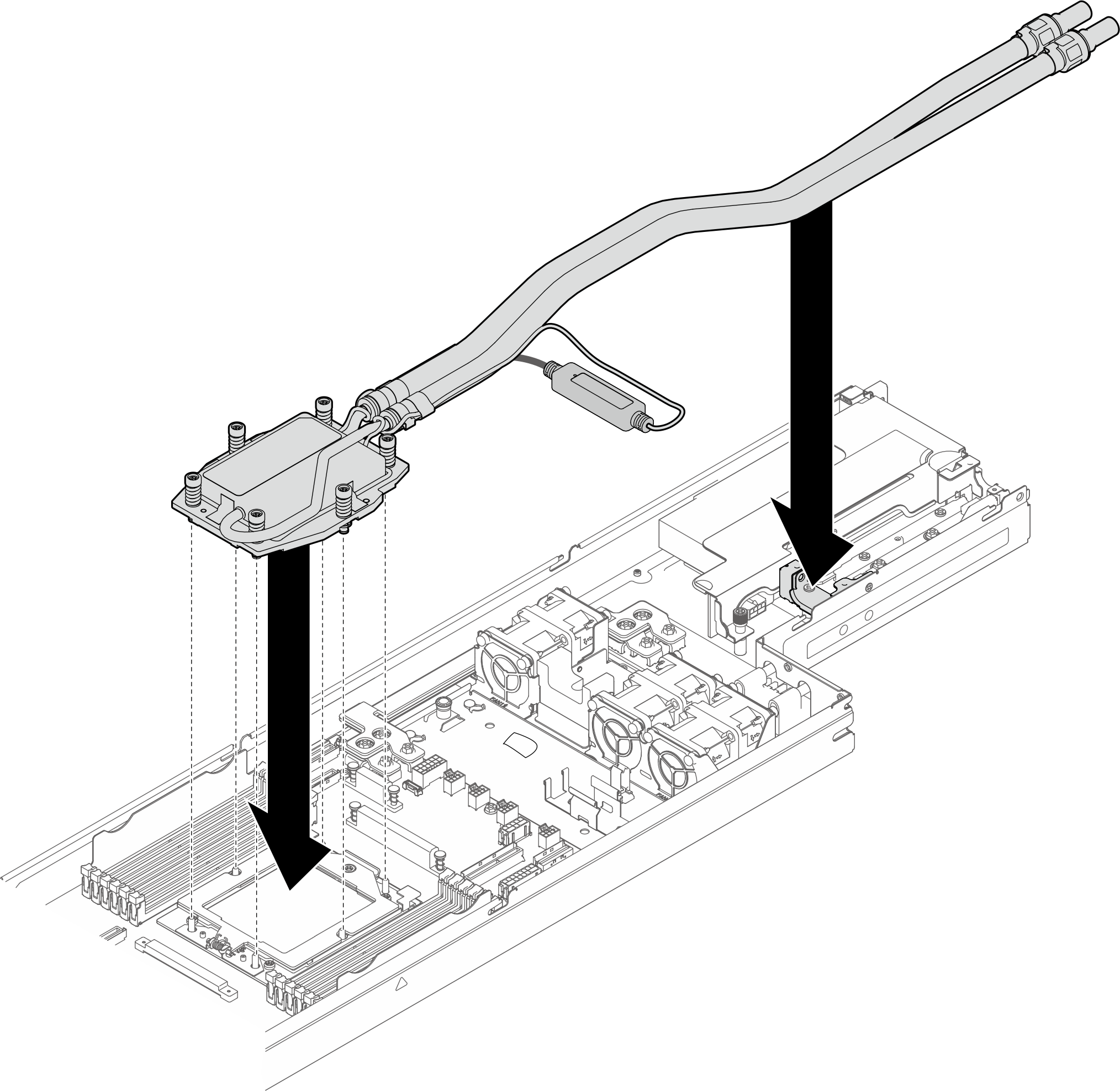
- Install the Processor Neptune® Core Module.
- Align the cold plate to the processor socket; then, carefully lower the Processor Neptune® Core Module into the chassis.Figure 3. Place the module
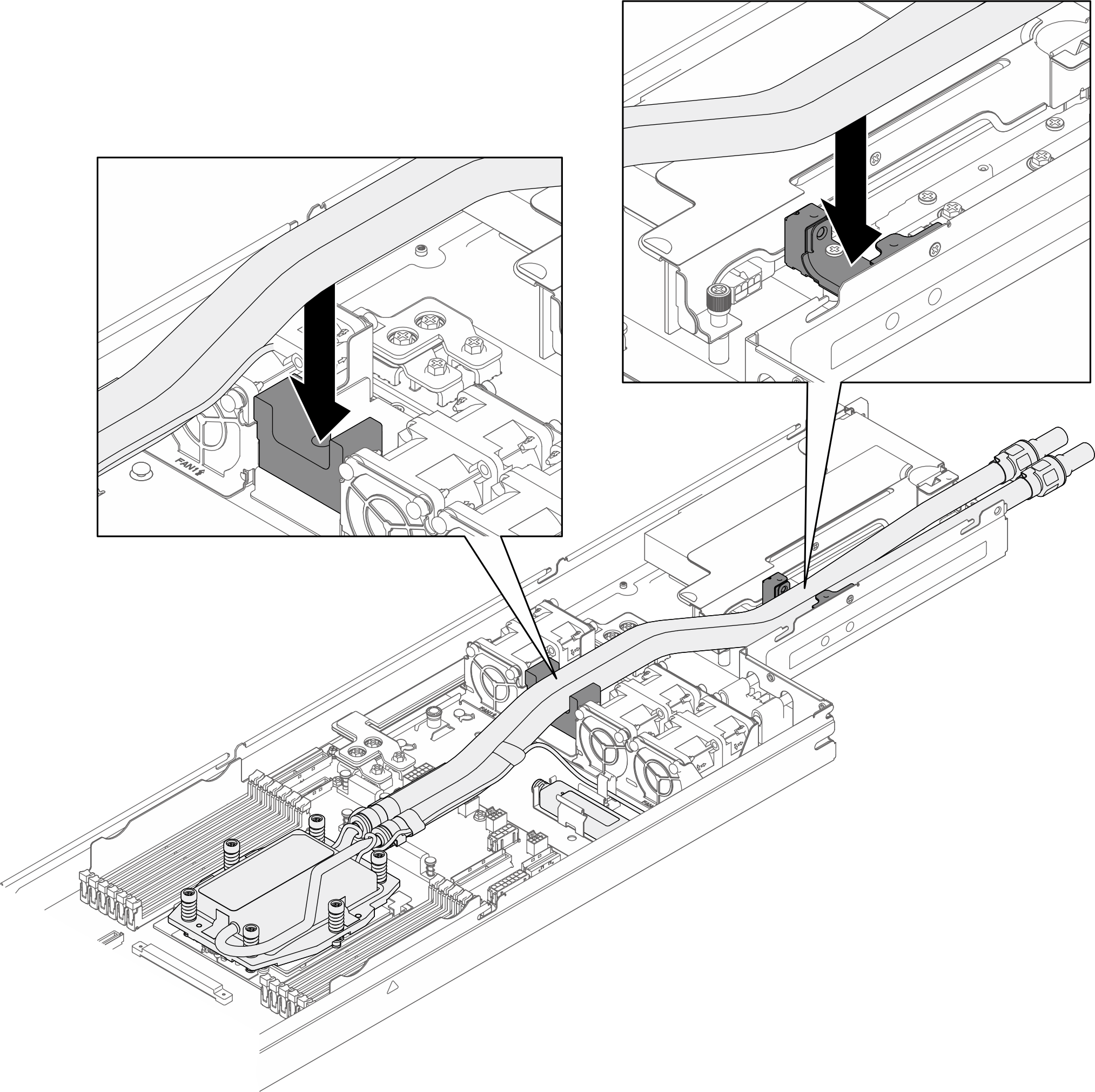
- Install the hoses to the hose holders.Figure 4. Installing the hoses
- Align the cold plate to the processor socket; then, carefully lower the Processor Neptune® Core Module into the chassis.
- Install the cold plate.
- Fully tighten all the screws in the installation sequence shown on the cold plate assembly.NoteFor reference, the torque required for the fasteners to fully tighten is 1.22-1.46 newton-meters (10.8-13.0 inch-pounds).Figure 5. Install the cold plate
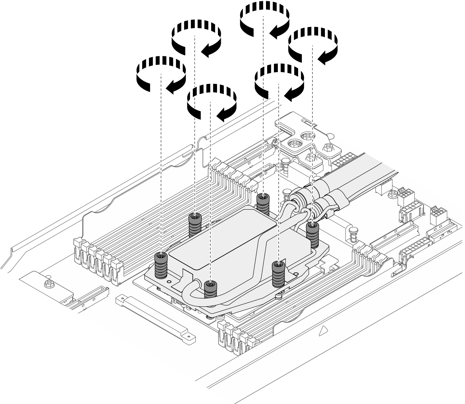
- Fully tighten all the screws in the installation sequence shown on the cold plate assembly.
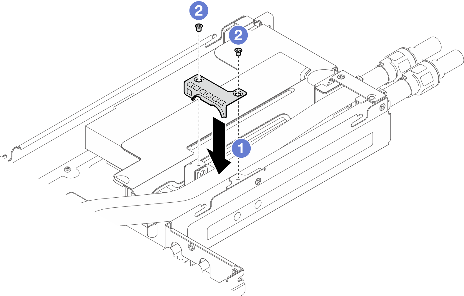
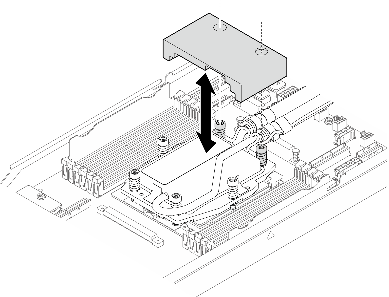
- Install the first hose cover.
- Align and install the hose cover to the slot.
- Fasten the two screws to secure the hose cover to the chassis.Figure 6. Installing the hose cover
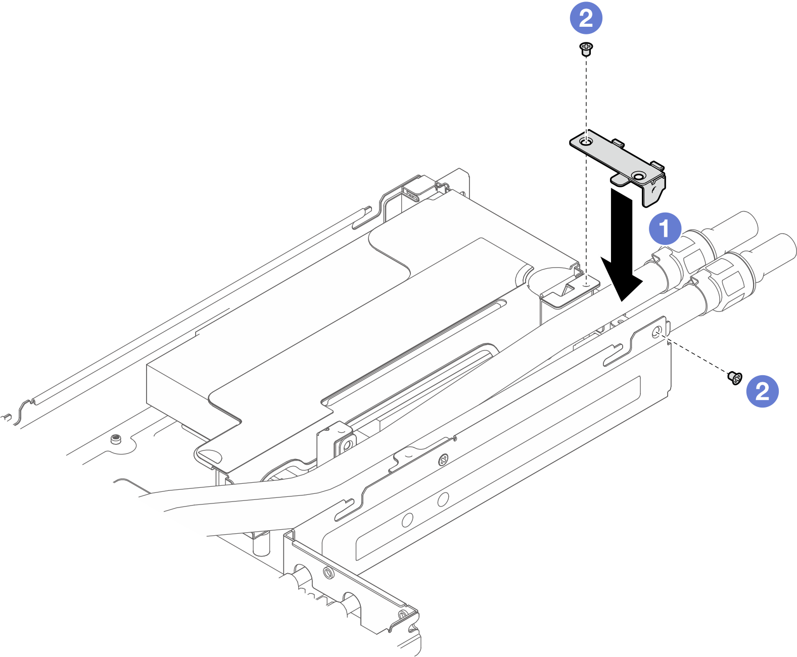
- Install the second hose cover.
- Align and install the hose cover to the opening on the rear of the chassis.
- Fasten the two screws to secure the hose cover to the chassis.Figure 7. Installing the hose cover
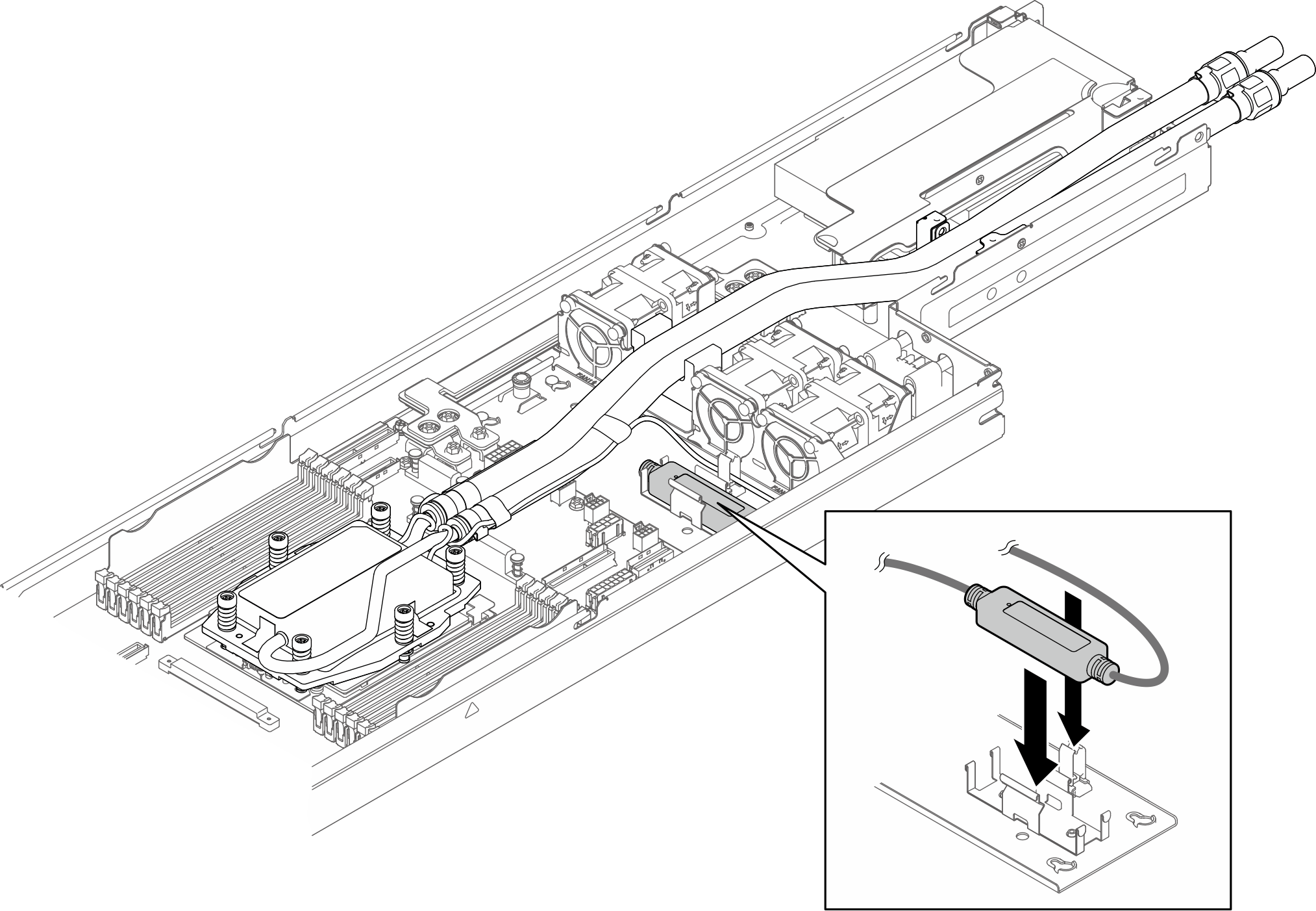
- Install the leakage sensor module to the sensor module holder.Figure 8. Installing the leakage sensor module
 Note
NoteFor leakage sensor module working status, see Leakage sensor module LED.
- Install the rubber air baffle onto the cold plate.Figure 9. Installing the rubber air baffle
 Note
NoteFor leakage sensor module working status, see Leakage sensor module LED.
After you finish
- Connect the cable of the leakage sensor module to the connector on the system board. See Leakage sensor module cable routing.
- Install the quick connect plugs to the manifolds. See Install the manifold (in-rack system) or Install the manifold (in-row system).
- Make sure that all the required cables are routed and connected correctly; then, reinstall the top cover (see Install the top cover).
- Reinstall the node into the chassis (see Install a node to the chassis).
- Make sure that the required power supply units are installed and power cords are connected; then, power on the node (see Install a hot-swap power supply and Power on the node).
- Proceed to complete the parts replacement (see Complete the parts replacement).
Demo video
Give documentation feedback