
Remove the system board (Trained technician only)

Follow instructions in this section to remove the system board.

Important
  • This task must be operated by trained technicians that are certified by Lenovo Service. Do not attempt to remove or install the part without proper training and qualification.

  • When replacing the system board, always update the server with the latest firmware or restore the pre-existing firmware. Make sure that you have the latest firmware or a copy of the pre-existing firmware before you proceed.
  • When removing the memory modules, label the slot number on each memory module, remove all the memory modules from the system board assembly, and set them aside on a static-protective surface for reinstallation.
  • When disconnecting cables, make a list of each cable and record the connectors the cable is connected to, and use the record as a cabling checklist after installing the new system board assembly.

About this task

To avoid potential danger, make sure to read and follow the safety information.

Attention

Read Installation Guidelines and Safety inspection checklist to make sure that you work safely.

Procedure

  1. Make preparations for this task.
    1. Record all system configuration information, such as Lenovo XClarity Controller IP addresses, vital product data, and the machine type, model number, serial number, Universally Unique Identifier, and asset tag of the server.
    2. Save the system configuration to an external device with Lenovo XClarity Essentials.
    3. Save the system event log to external media.
    4. Power off the node (see Power off the node); then, disconnect all external cables from the node.
    5. Remove the node from the chassis (see Remove a node from the chassis); then, carefully lay the node on a flat, static-protective surface, orienting the node with the front toward you.
      Note
      • When removing the node, note the node tray number and make sure to install the node in the same tray from which it was removed. Reinstalling the node into a different tray requires the node to be reconfigured.
      • For safety, make sure to hold the node with both hands when lifting the node.
    6. Remove the top cover (see Remove the top cover).
    7. Disconnect all the cables from the drive backplane.
    8. Remove the processor and heat sink (see Remove the processor and heat sink).
    9. Remove the firmware and RoT security module (see Remove the firmware and RoT security module).
    10. Make sure to label the slot number on each memory module; then, remove all the memory modules from the system board and set them aside on a static-protective surface for reinstallation (see Remove a memory module).
      Important
      It is advised to print out the layout of memory module slots for reference.
    11. If necessary, remove the M.2 drives (see Remove an M.2 drive).
    12. Remove the microSD card (see Remove the MicroSD card).
    13. If the GPU air duct is installed in the node, remove it (see Remove the GPU air duct).
    14. If the PCIe riser assembly is installed, remove it from the node and disconnect the PCIe cables from the system board (see Remove the PCIe riser assembly and Internal cable routing).
    15. Remove the power bus bar (see Remove the power bus bar).
    16. Disconnect the power distribution board cables from the system board; then, remove the power distribution board (see Remove the power distribution board).
    17. If the rear OCP and rear I/O module cables are connected to the system board, remove them (see Rear I/O and OCP module cable routing).
  2. Disconnect all the cables from the system board. When disconnecting the cables, make a list of each cable and record the connectors the cables are connected to, and use the record as a cabling checklist after installing the new system board.
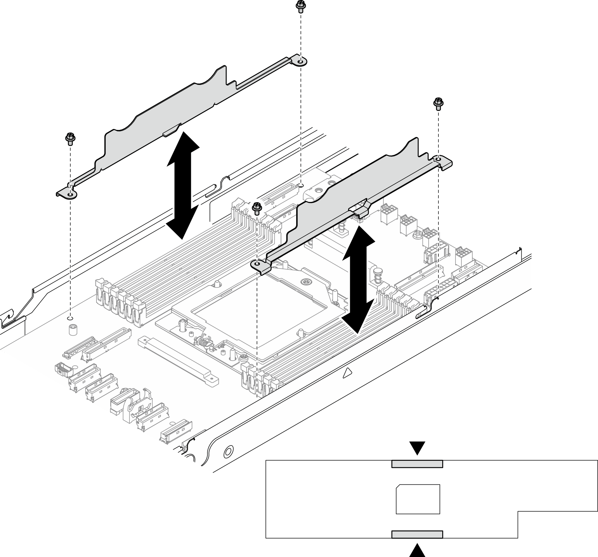
  3. Loosen the screws that secure the cable walls and lift them out of the node.
    Figure 1. Cable wall replacement
    Cable wall replacement
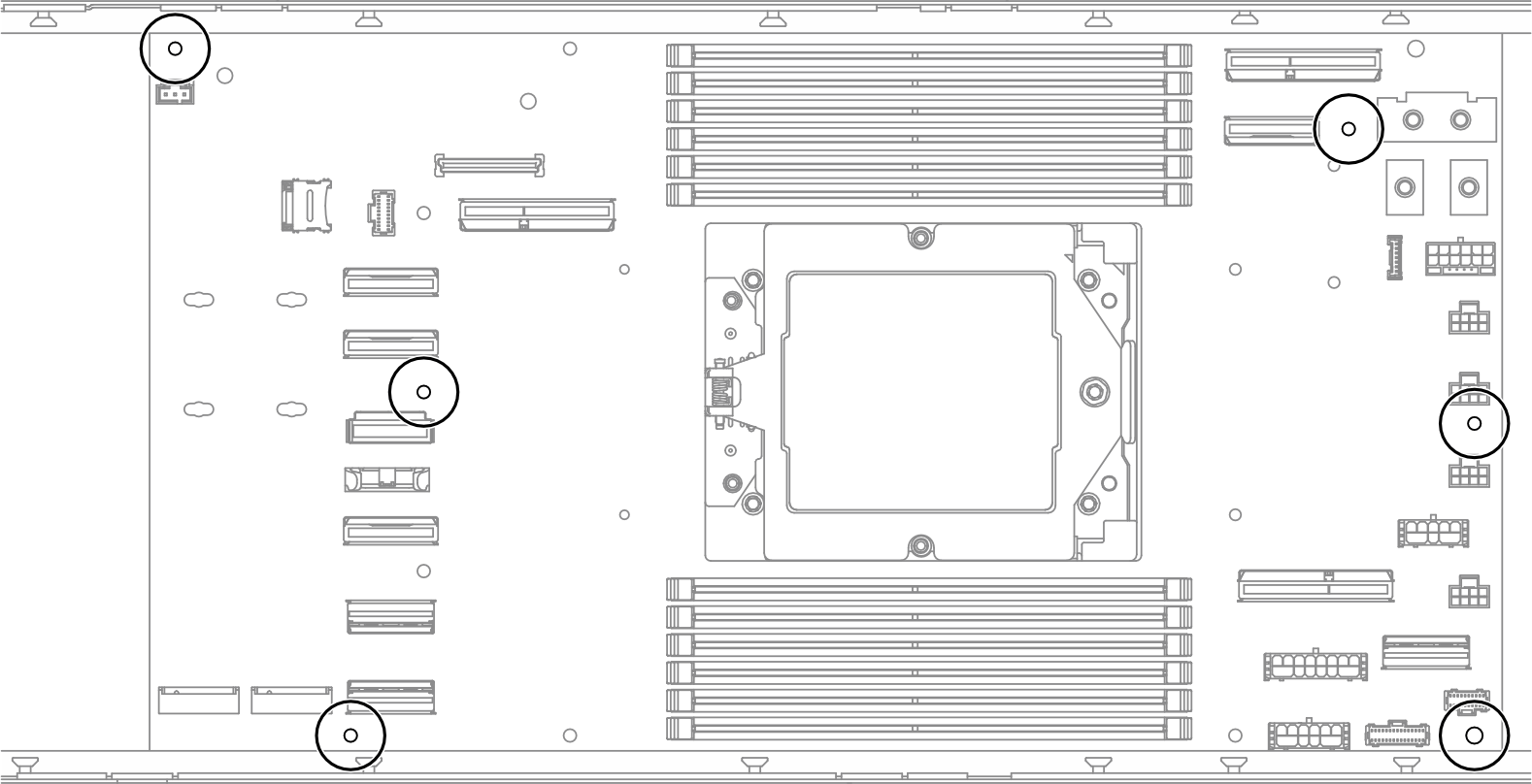
  4. Remove all the screws from the system board.
    Important
    When removing the system board from the node, avoid touching the connectors on the system board. Do not damage any surrounding components inside the node.
    Figure 2. Removal of the screws
    System board removal
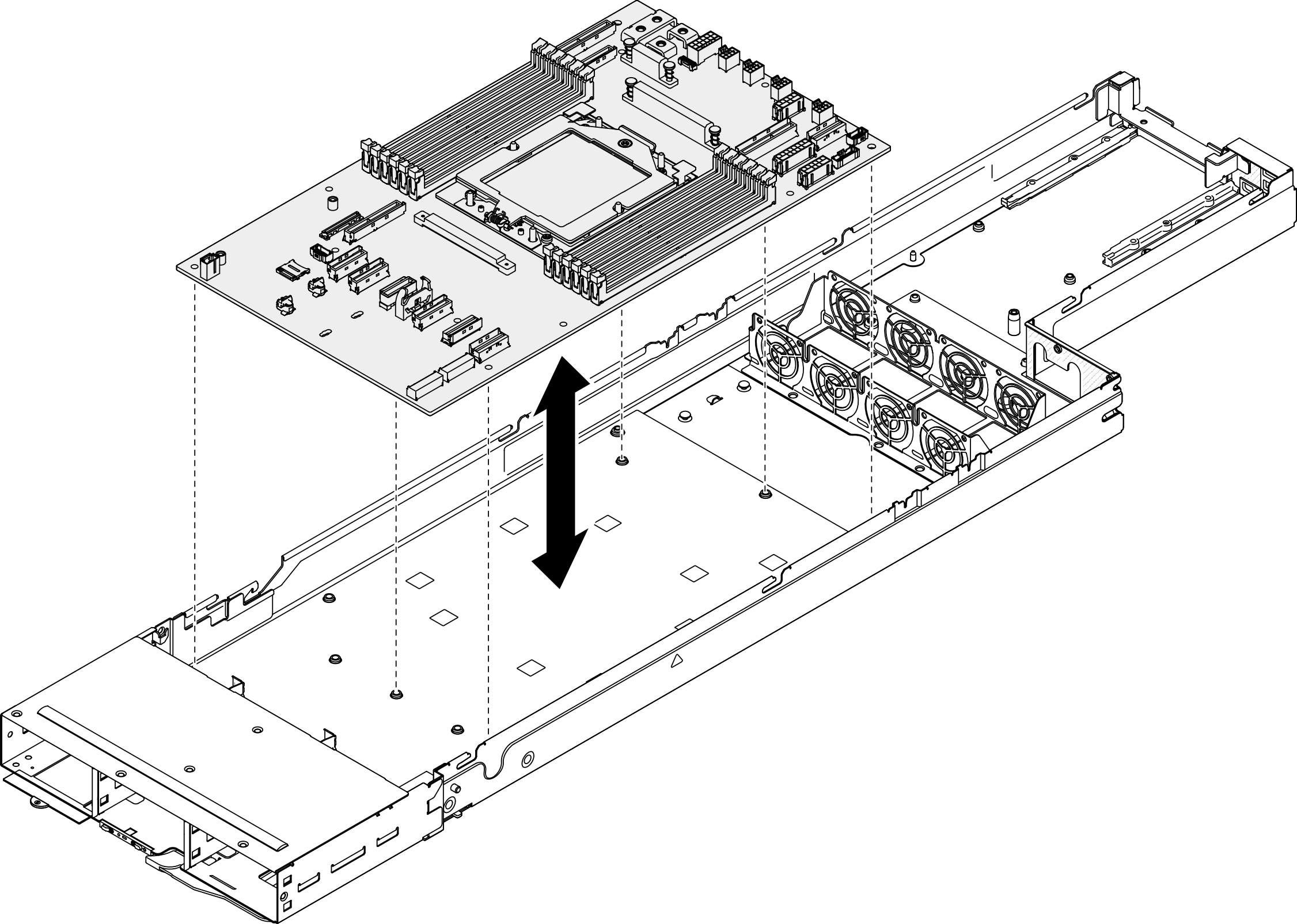
  5. Carefully lift the system board out of the node
    Figure 3. Removal of the system board
    System board removal

After this task is completed

  1. Install a replacement unit (see Install a system board (Trained technician only)).
  2. If you are instructed to return the component or optional device, follow all packaging instructions, and use any packaging materials for shipping that are supplied to you.
    Important
    Before returning the system board, make sure to install the processor socket covers from the new system board. Follow the steps below to replace a processor socket cover:
    1. Take a socket cover from the processor socket assembly on the new system board and orient it correctly above the processor socket assembly on the removed system board.
    2. Gently press down the socket cover legs to the processor socket assembly, pressing on the edges to avoid damage to the socket pins. You might hear a click on the socket cover when it is securely attached.
    3. Make sure that the socket cover is securely attached to the processor socket assembly.