Install a firmware and RoT security module
Follow instructions in this section to install a firmware and RoT security module (ThinkSystem V3 Firmware and Root of Trust Security Module).
About this task
This task must be operated by trained technicians that are certified by Lenovo Service. Do not attempt to remove or install the part without proper training and qualification.
(Lenovo trained technician only) After replacing the firmware and RoT security module, update the UEFI firmware to the specific version supported by the server.
To avoid potential danger, make sure to read and follow the safety information.
Read Installation Guidelines and Safety inspection checklist to make sure that you work safely.
Touch the static-protective package that contains the component to any unpainted metal surface on the node and chassis; then, take the component out of the package and place it on a static-protective surface.
Go to Drivers and Software download website for ThinkSystem SD535 V3 to see the latest firmware and driver updates for your server.
Go to Update the firmware for more information on firmware updating tools.
Procedure
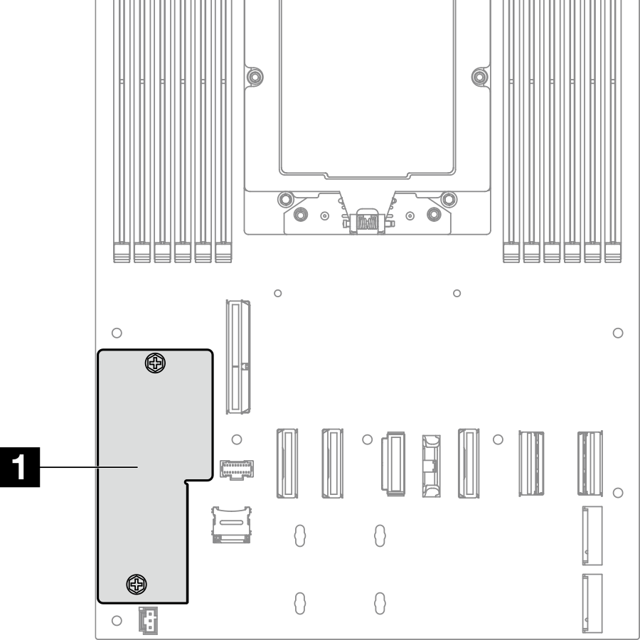
- Locate the Firmware and RoT security module connector on the system board.Figure 1. Location of the Firmware and RoT security module
- Install the firmware and RoT security module to the node.
 Lower the firmware and RoT security module onto the system board and make sure that the connector on the module is correctly inserted into the slot on the system board.
 Tighten the two screws to secure the firmware and RoT security module.Figure 2. Installation of the firmware and RoT security module
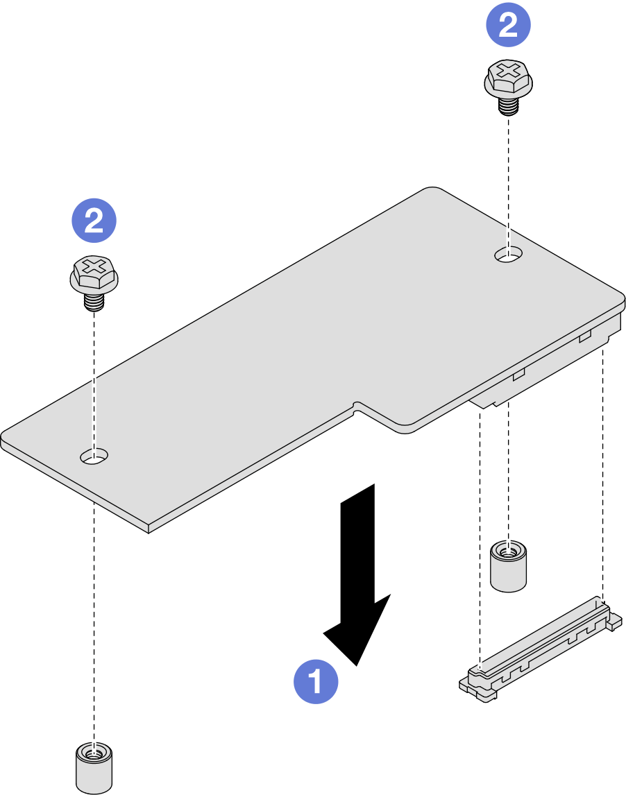
After you finish
- Reinstall the processor heat sink (see Install a processor and heat sink).ImportantThis task must be operated by trained technicians.
- Make sure that all the required cables are routed and connected correctly; then, reinstall the top cover (see Install the top cover).
- Reinstall the node into the chassis (see Install a node to the chassis).
- Make sure that the required power supply units are installed and power cords are connected; then, power on the node (see Install a hot-swap power supply and Power on the node).
- Proceed to complete the parts replacement (see Complete the parts replacement).
- Update the UEFI, XCC and LXPM firmware to the specific version supported by the server. See Tip for replacing a Firmware and RoT Security Module (Lenovo service technicians only).
- Perform OneCLI commands or XCC actions to restore the UEFI and XCC settings. See OneCLI commands that restore configuration settings or Using XCC to restore the BMC configuration.
- Optionally, do the following if needed:
- Hide TPM. See Hide/observe TPM.
- Update the TPM firmware. See Update the TPM firmware.
- Enable UEFI Secure Boot. See Enable UEFI Secure Boot.
Demo video