安装歧管(机架级系统)
按以下信息将歧管安装在机架级直接水冷系统中。
关于本任务
重要
本任务必须由经过 Lenovo 服务机构认证的训练有素的技术人员执行。如果没有经过相关培训或不具备相应资质,请勿尝试拆卸或安装该部件。
首次安装该部件时,请联系 Lenovo 专业服务团队以获取帮助。
警告
冷却液可能会引起皮肤和眼睛不适。请避免直接接触冷却液。
S002
警告
设备上的电源控制按钮和电源上的电源开关不会切断设备的供电。设备也可能有多根电源线。要使设备彻底断电,请确保从电源上拔下所有电源线。
S011

警告
附近有尖锐的边缘、边角或接点。
S038

警告
此过程应佩戴护目装置。
S040

警告
此过程应佩戴保护手套。
S042

危险
危险
本产品中存在水或水溶液,因此会有触电危险。请避免用湿手或在有溅水的情况下操作或靠近带电设备。
注意
关闭节点电源(请参阅关闭节点电源);然后,从节点上拔下所有外部线缆。
为避免静电导致的系统中止和数据丢失,请在安装前将容易被静电损坏的组件放在防静电包装中,并在操作设备时使用静电释放腕带或其他接地系统。
操作机架散热系统中使用的任何经化学处理的冷却液时,请确保遵循正确的处理过程。请确保冷却液化学处理供应商提供了材料安全数据表(MSDS)和安全信息,且具有冷却液化学处理供应商建议的恰当个人防护设备(PPE)。作为预防措施,建议使用防护手套和眼镜。
本任务需要两个或两个以上的人员完成。
过程
- 安装歧管。图 1. 安装歧管
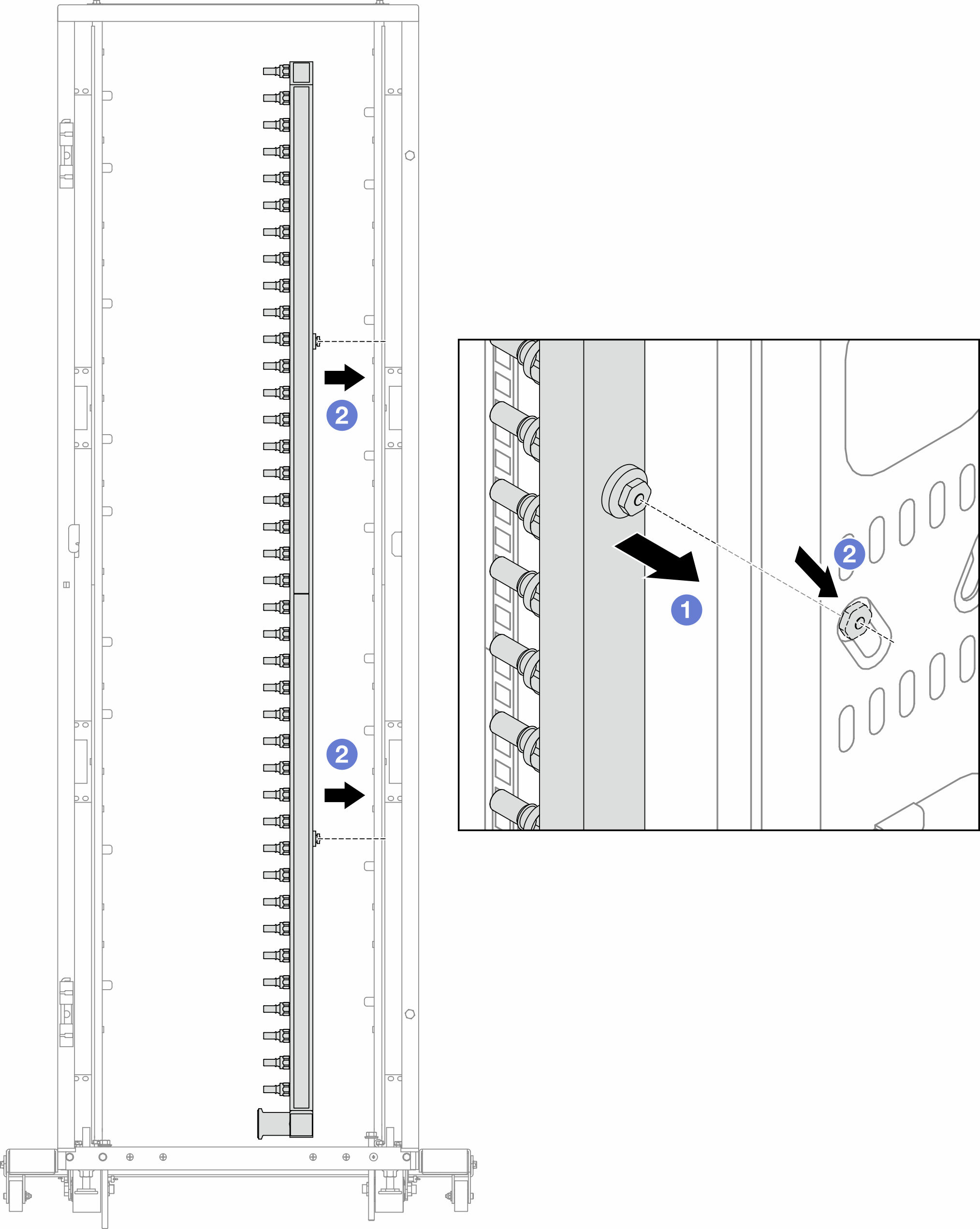
 用双手握住歧管,并将其安装到机架机柜上。
 将线轴与孔对齐,然后握紧机柜。
注有关机架机柜的更多信息,请参阅《ThinkSystem Heavy Duty Full Depth 机架机柜用户指南》。 - 将球阀安装到 CDU。图 2. 安装球阀
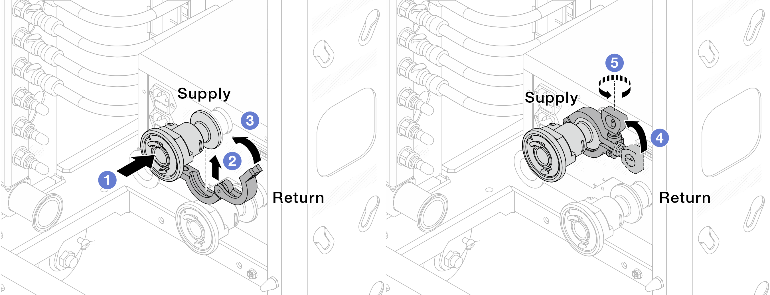
- 将球阀连接到供给端口和回流端口。
- 用夹钳将接口包裹起来。
 合上夹钳。
合上夹钳。 将螺钉竖直提起。
 拧紧螺钉并确保其已固定。
- 将连接套件安装到歧管上。图 3. 安装连接套件
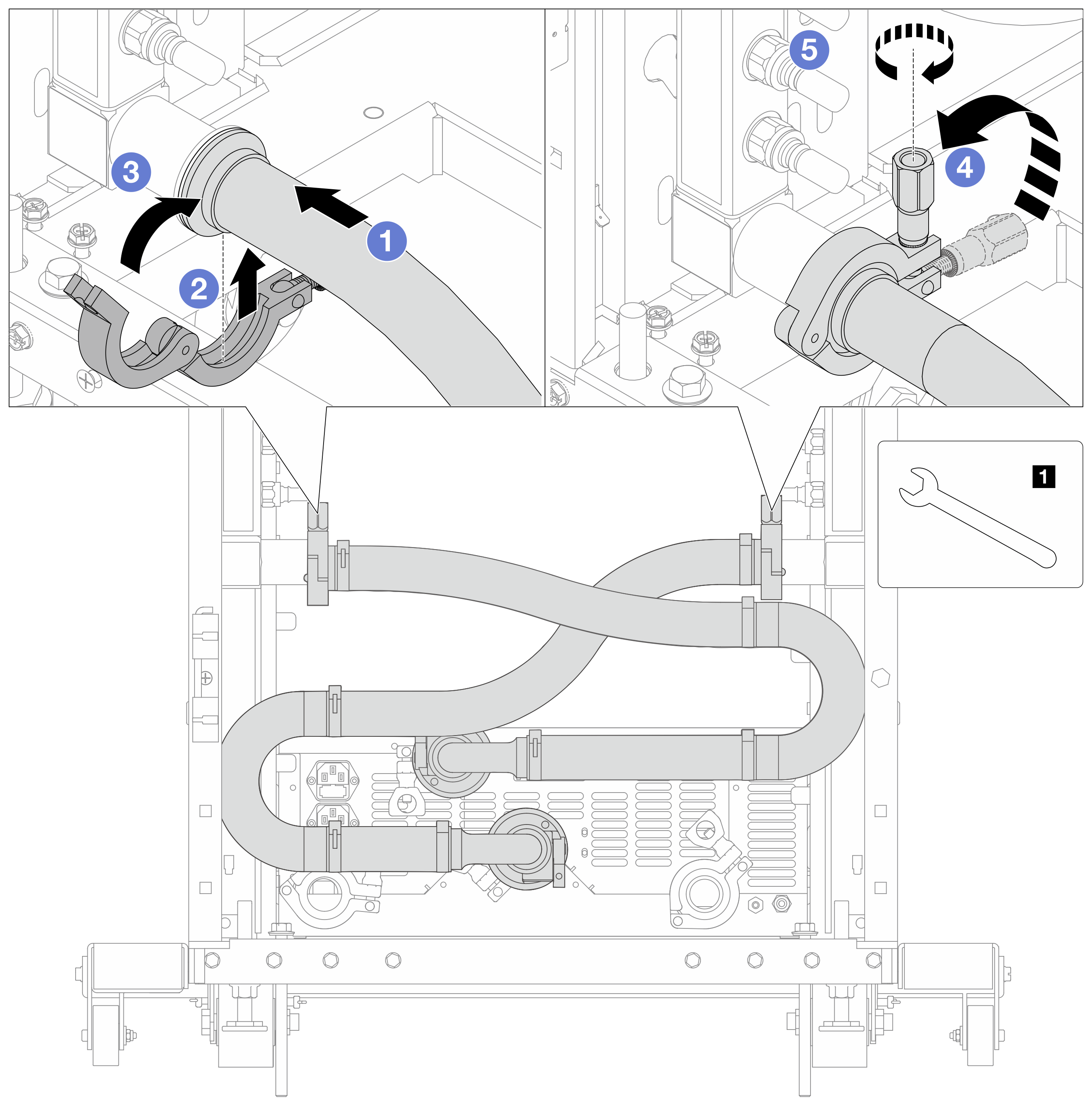
1 17 毫米扳手 - 将连接套件连接到两个歧管。
- 用夹钳将接口包裹起来。
- 合上夹钳。
- 将螺钉竖直提起。
- 拧紧螺钉并确保其已固定。
- 将连接套件安装到球阀上。图 4. 连接球阀
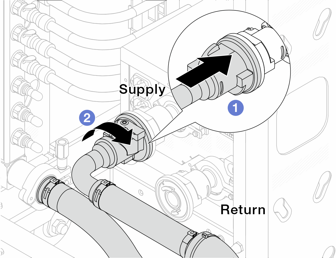
- 连接球阀。
- 向右旋转以锁定两个球阀。
- 准备机架级 CDU。
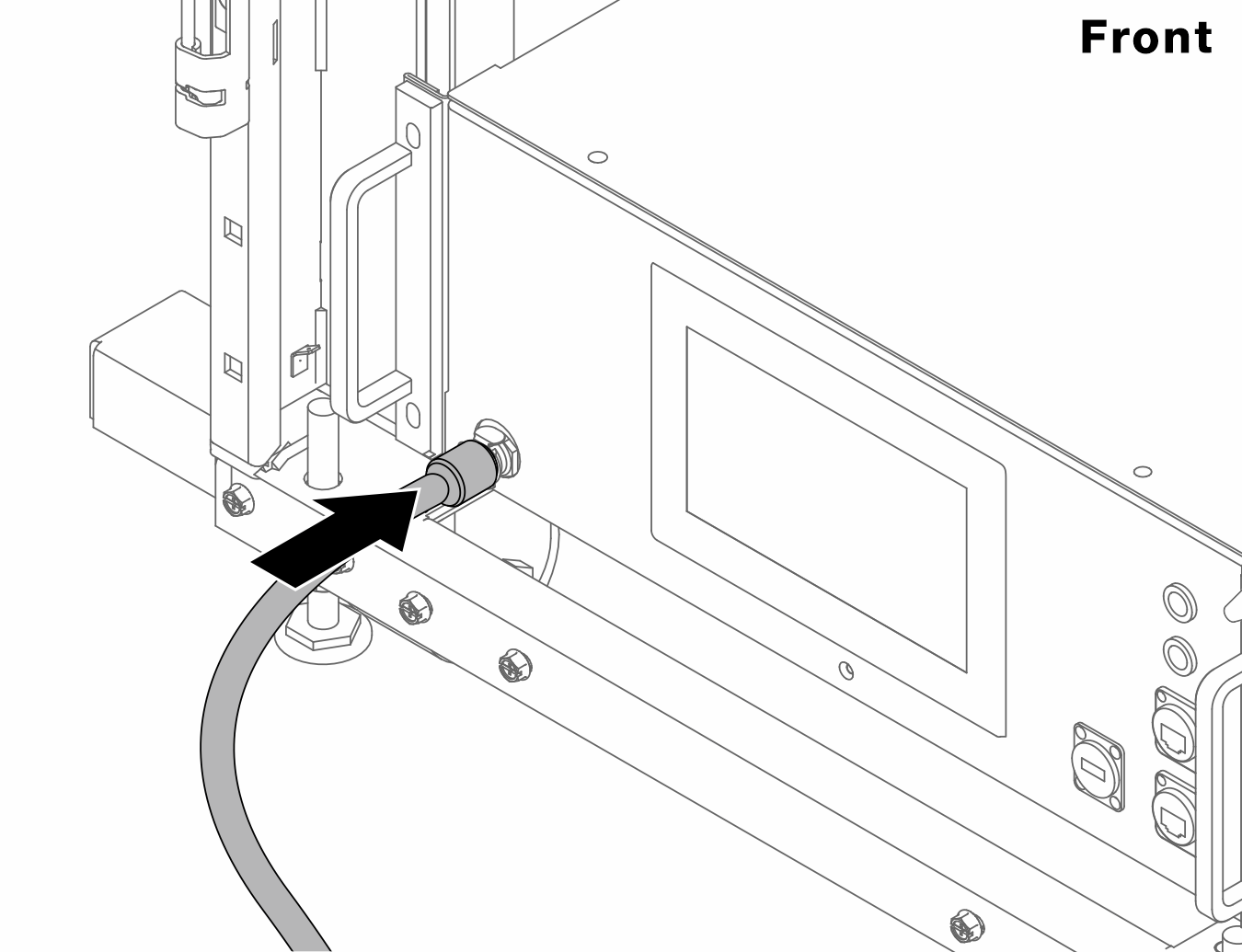
- 将供给软管连接到正面的入口。图 5. CDU 正面
- 将软管连接到背面的排水端口和排气端口。图 6. CDU 背面
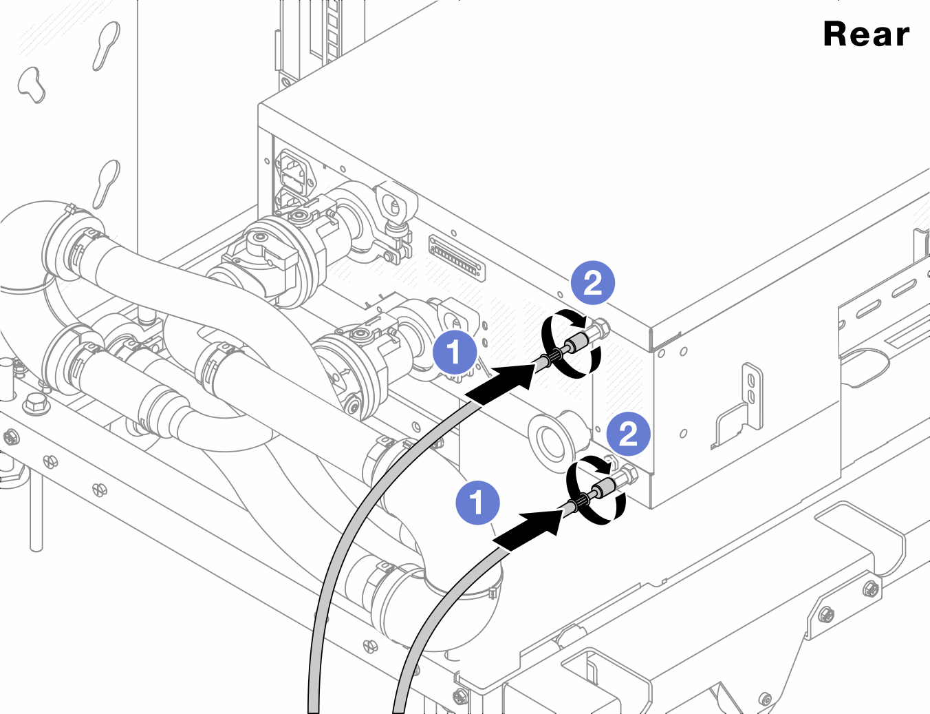
- 将排水软管和排气软管连接到 CDU。
- 向右旋转接口以固定连接。
重要如需了解更多操作和维护指南,请参阅《Lenovo Neptune DWC RM100 机架级冷却液分配单元(CDU)操作和维护指南》。
- 如需服务支持、相关保修和维护规模信息,请联系 Lenovo Professional Services 团队:
cdusupport@lenovo.com
- 将供给软管连接到正面的入口。
- 将快接插头安装到歧管上。图 7. 安装快接插头
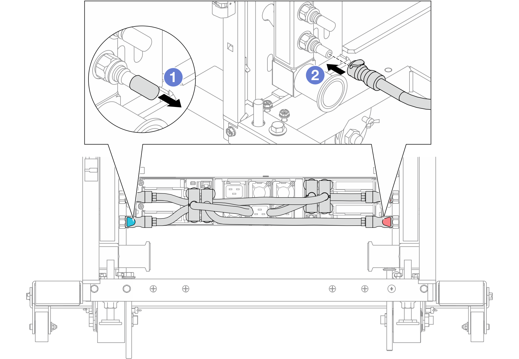
- 从歧管端口上卸下橡胶快接插头外盖。
- 将插头连接至歧管端口。
- 将排气套件安装到歧管供给侧。图 8. 将排气套件安装到供给侧
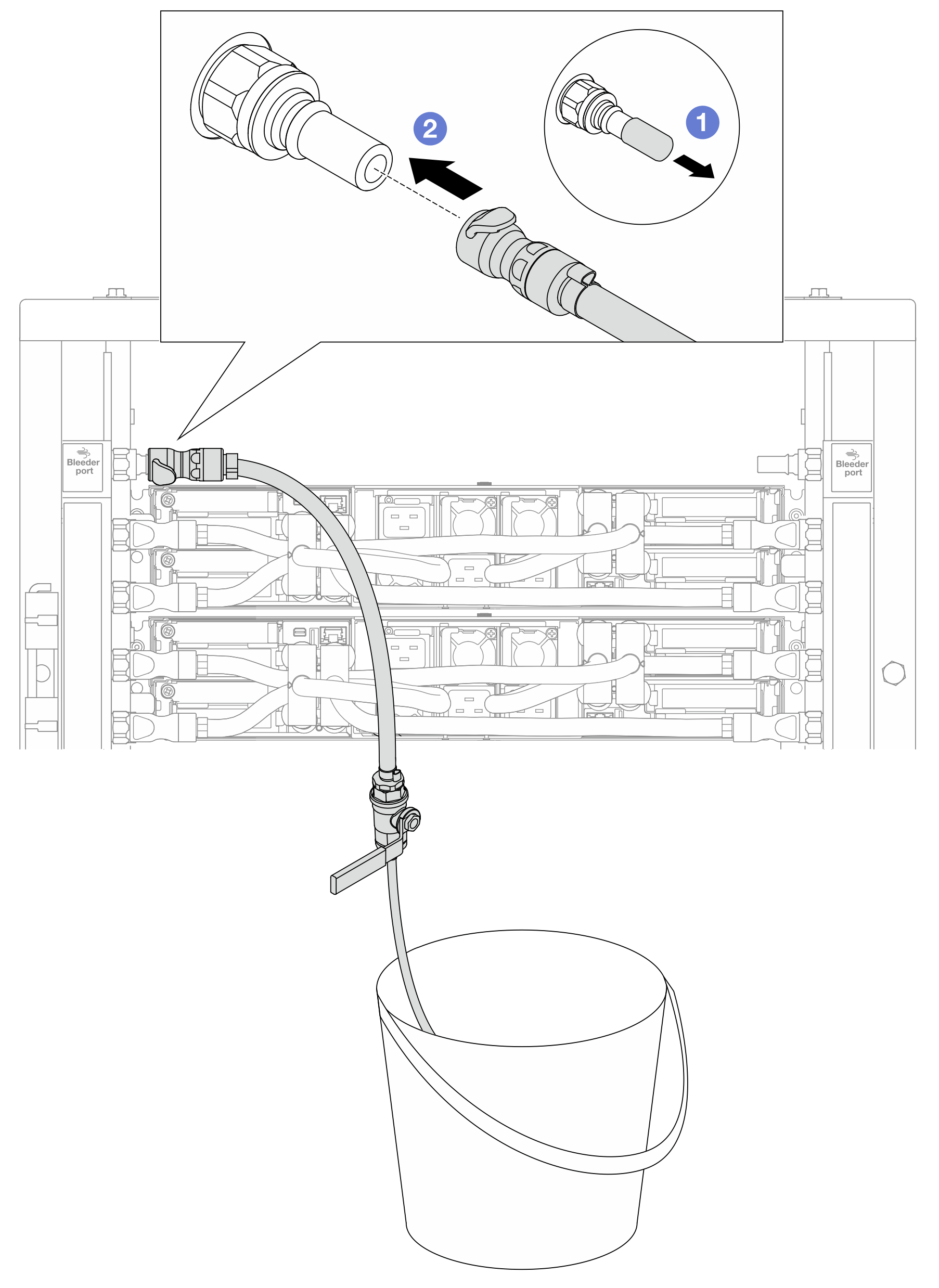
- 从歧管端口上卸下橡胶快接插头外盖。
- 将排气套件插入歧管。
- 要将空气从歧管中推出,请打开球阀开关,让冷却液充满系统。图 9. 打开球阀
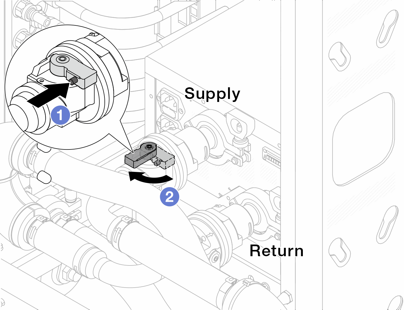
- 按下球阀开关上的按钮。
- 旋转开关以完全打开阀门,如上图所示。
注意密切关注 CDU 正面显示结果,保持系统压力在 1 巴。
有关冷却液温度和系统压力要求的更多信息,请参阅冷却水要求。
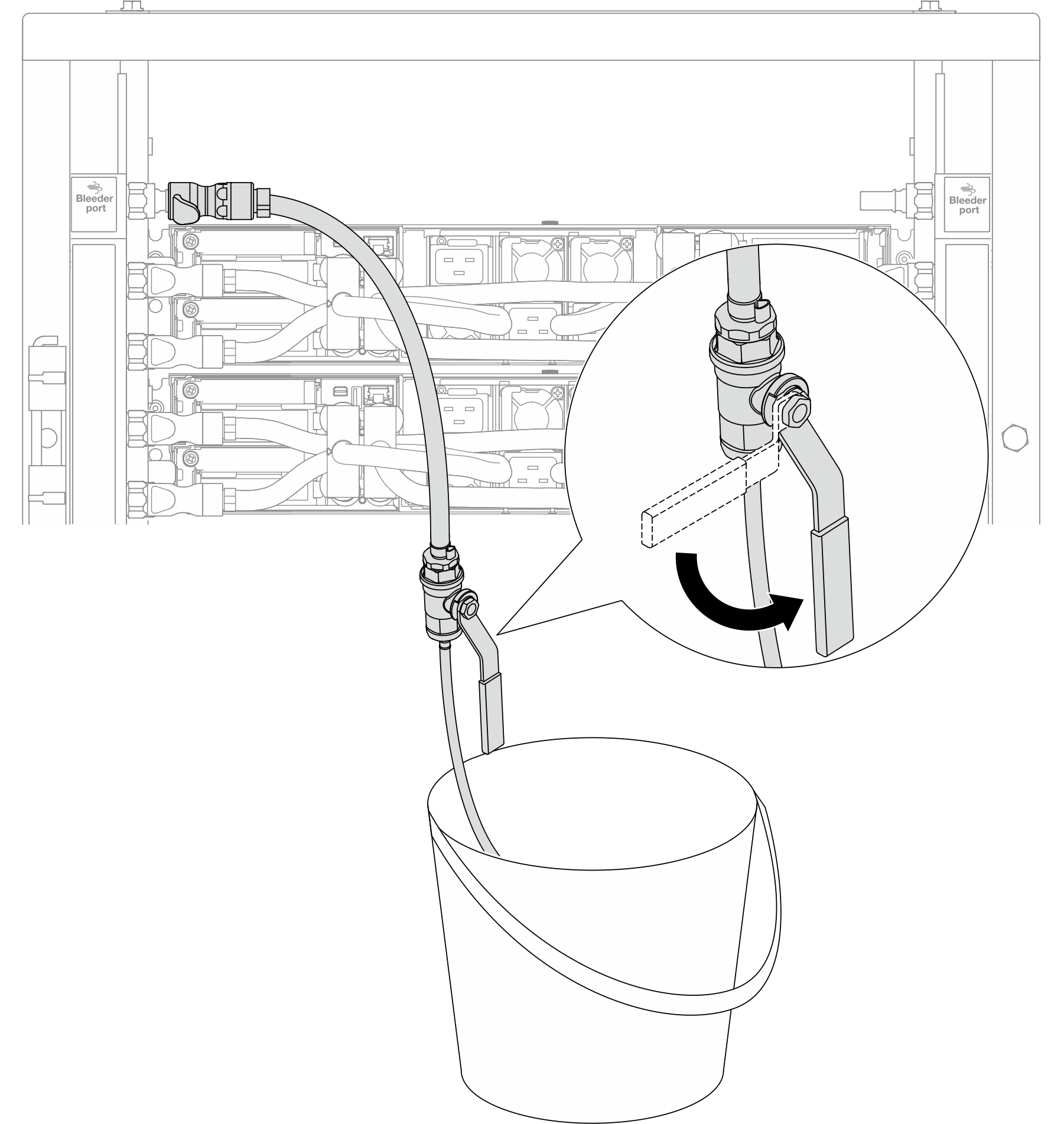
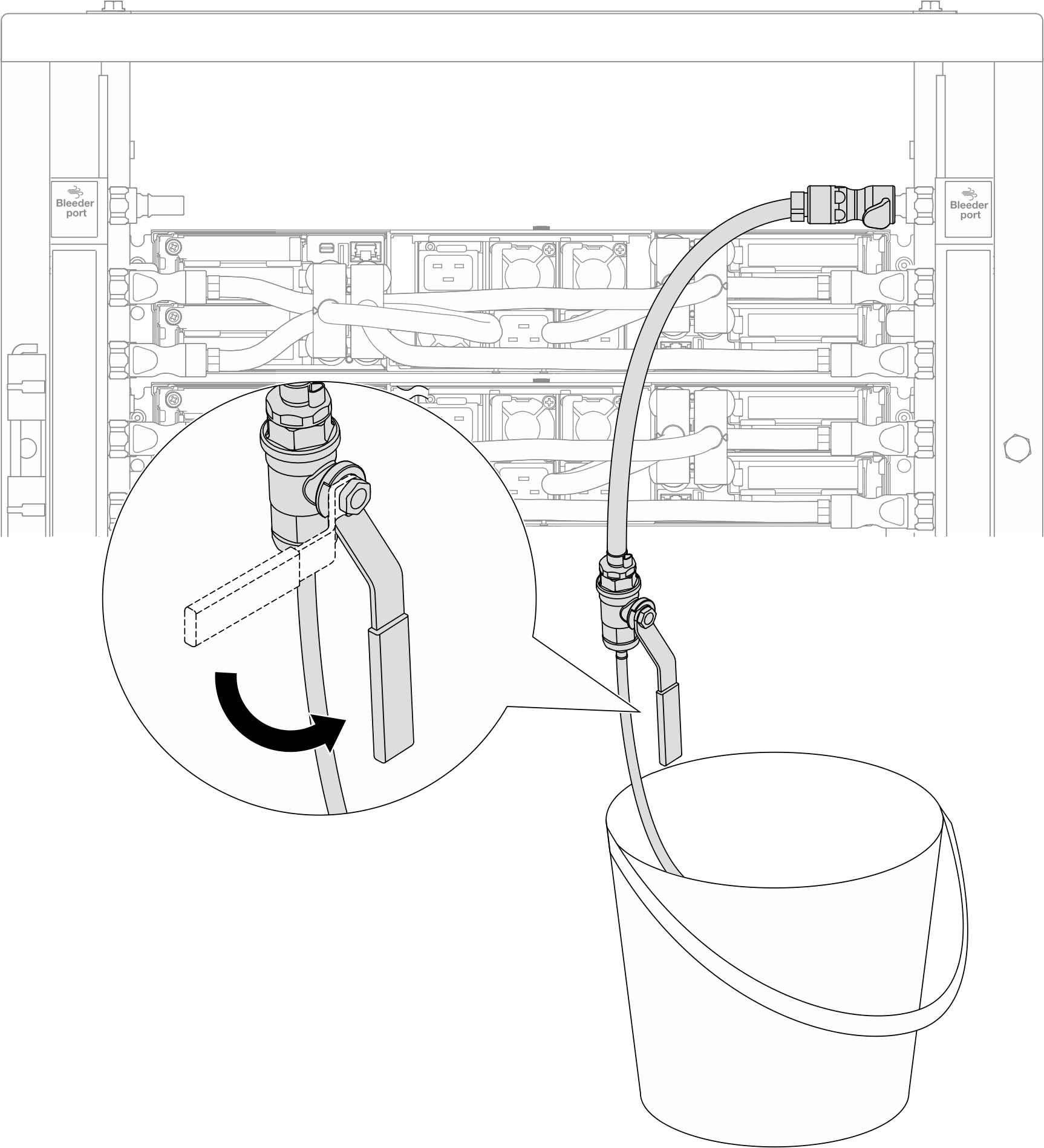
- 缓慢打开排气阀门,以便将软管中的空气排出。当有稳定的水流流入水桶或排气软管中只有极小的气泡时,关闭排气阀门。图 10. 打开供给侧的排气阀门
- 将排气套件安装到歧管回流侧。图 11. 将排气套件安装到回流侧
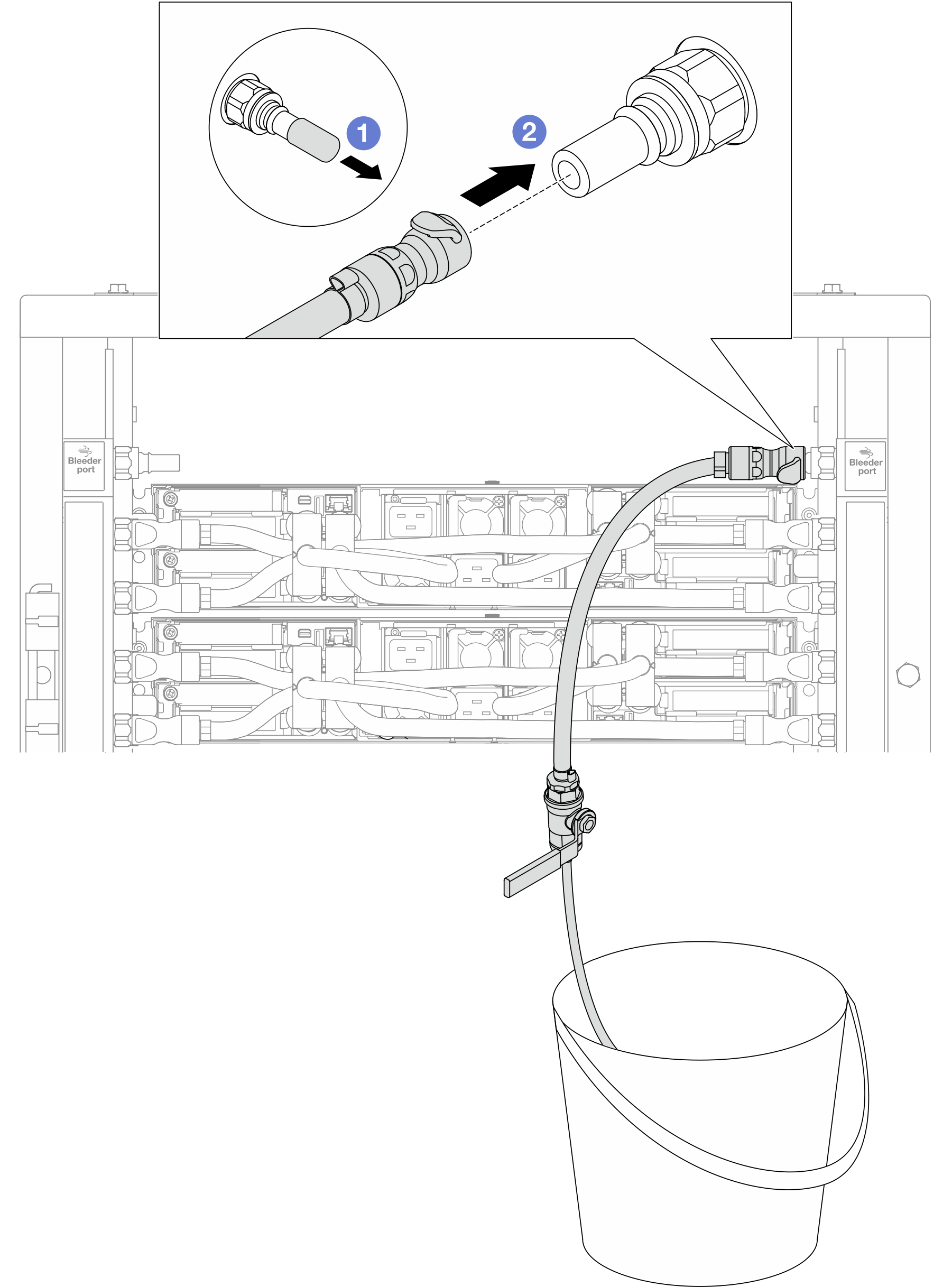
- 从歧管端口上卸下橡胶快接插头外盖。
- 将排气套件插入歧管。
- 缓慢打开排气阀门,以便将软管中的空气排出。当有稳定的水流流入水桶或排气软管中只有极小的气泡时,关闭排气阀门。图 12. 打开回流侧的排气阀门
- (预防措施)为确保内部空气尽可能少,请将排气套件重新安装回歧管供给侧并再操作一次。当有稳定的水流流入水桶或排气软管中只有极小的气泡时,关闭排气阀门。图 13. 打开供给侧的排气阀门
完成之后
完成部件更换。请参阅完成部件更换。
提供反馈