Install a drive backplane
Use this information to install a drive backplane.
Procedure
Install two backplanes for the configuration with two 7mm 2.5-inch SATA/NVMe solid-state drives:
- Install the lower backplane:
 Align the lower backplane with the lower backplane slot in the drive cage. Then, insert the backplane at an angle (approximately 20 degrees) into the slot until it is fully seated.
  Fasten the two screws and one standoff to secure the lower backplane.Figure 1. 7mm drive lower backplane installation
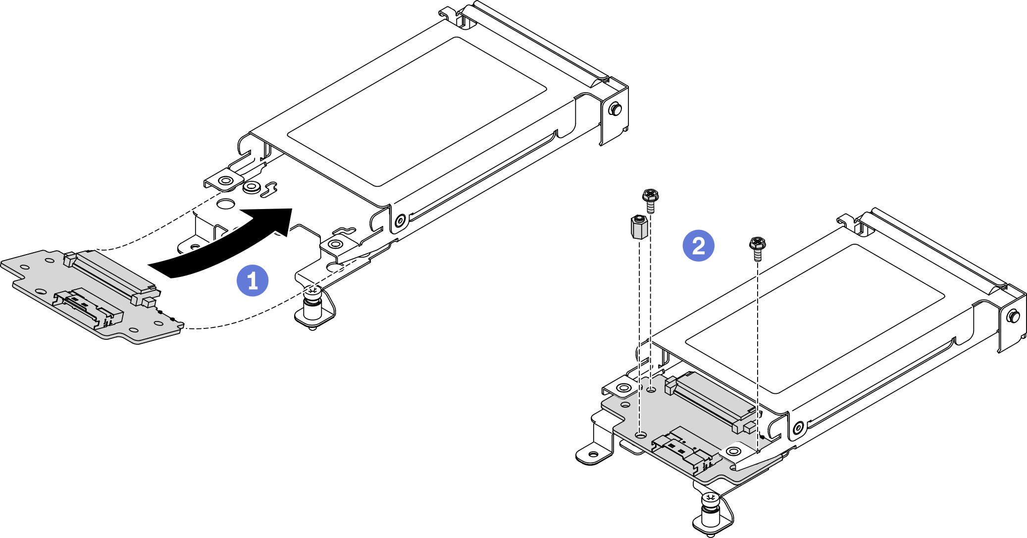
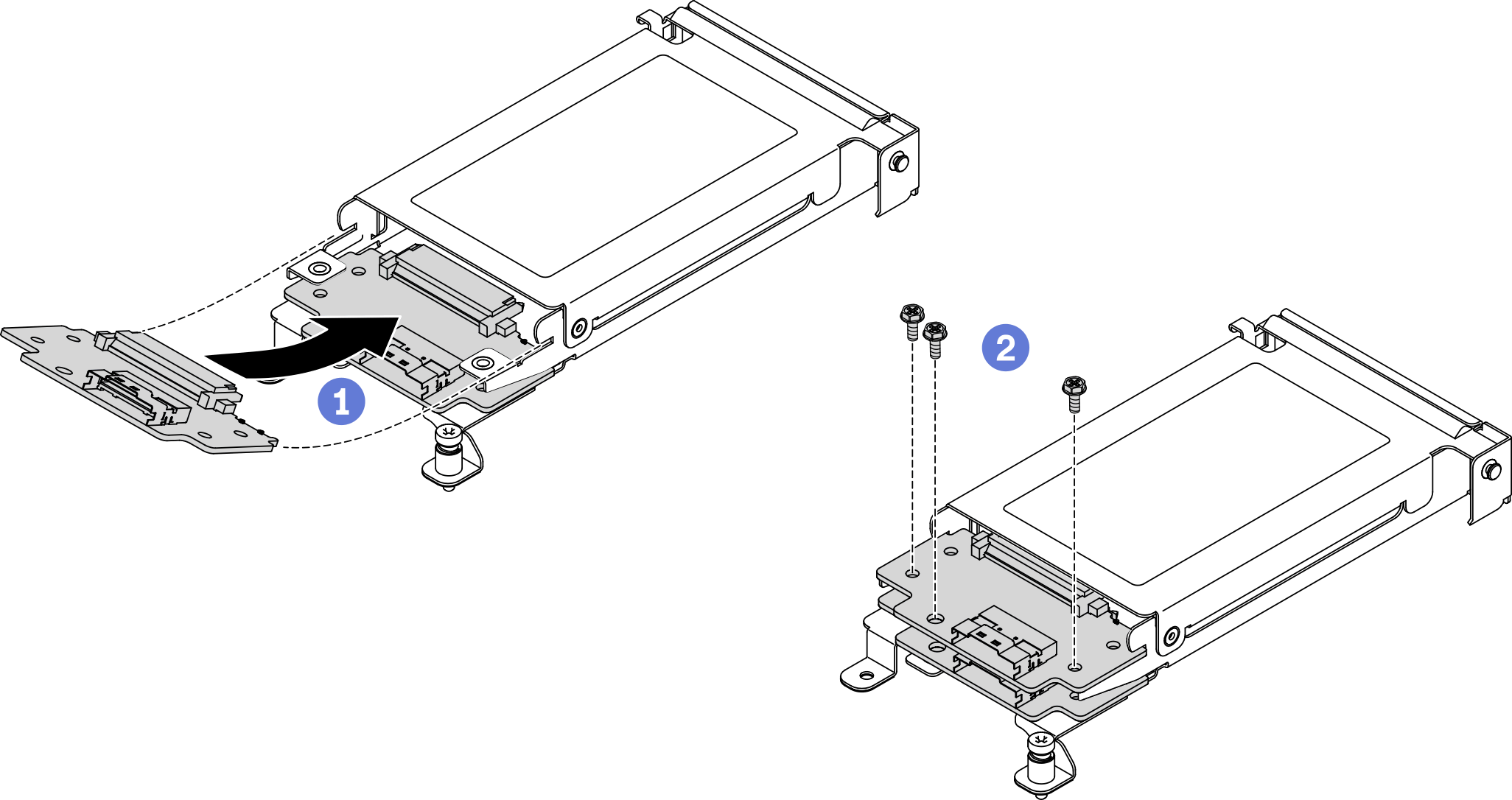
- Install the upper backplane: Align the upper backplane with the upper backplane slot in the drive cage. Then, insert the backplane at an angle (approximately 30 degrees) into the slot until it is fully seated. Fasten the three screws to secure the upper backplane.Figure 2. 7mm drive upper backplane installation
Install one backplane for the configuration with a 15mm 2.5-inch NVMe solid-state drive:
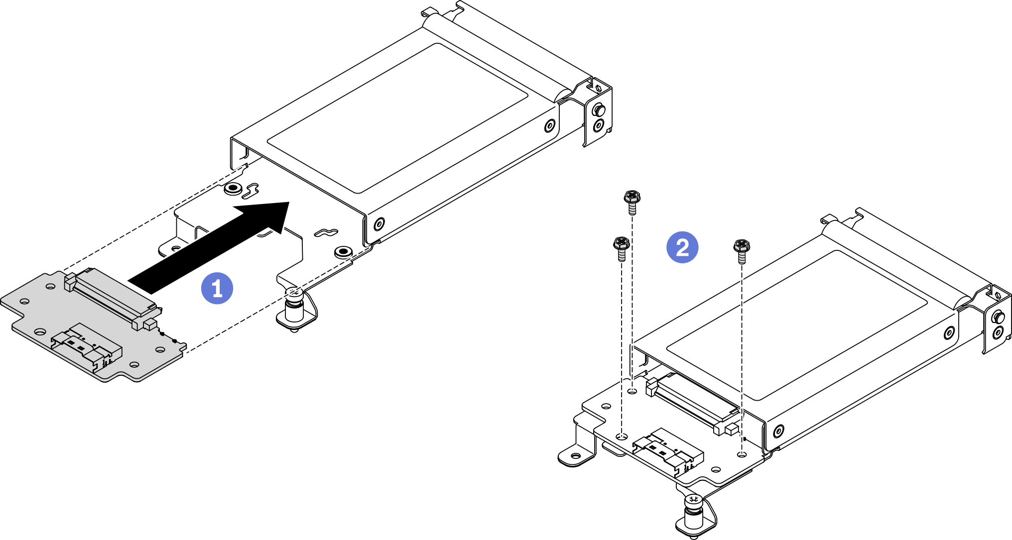
- Align the backplane with the backplane slots in the drive cage. Then, press the backplane into the slots until it is fully seated.
- Fasten the three screws to secure the backplane.Figure 3. 15mm drive backplane installation
After you finish
Reconnect the power cable to the system board and the signal cables to the drive backplane(s).
- Reinstall the components listed below into the compute node in the following order:
Drive cage assembly (see Install the drive cage assembly).
The cable connecting the system board and 7mm or 15mm drive backplanes (see 7mm 2.5-inch SATA/NVMe drive backplane cable or 15mm 2.5-inch NVMe drive backplane cable).
Drive(s) (see Install a hot-swap solid-state drive).
Node front cover (see Install the node front cover).
Reinstall the compute node into the enclosure (see Install a compute node in the enclosure).
Check the power LED on each node to make sure it changes from fast blink to slow blink to indicate the node is ready to be powered on.
Demo video