Remove a memory module
Use this information to remove a memory module. This section applies to both RDIMMs and 3DS RDIMMs.
About this task
- Read the Installation Guidelines to ensure that you work safely.
- Memory modules are sensitive to static discharge and require special handling. Refer to the standard guidelines for Handling static-sensitive devices.
Always wear an electrostatic-discharge strap when removing or installing memory modules. Electrostatic-discharge gloves can also be used.
Never hold two or more memory modules together so that they do not touch each other. Do not stack memory modules directly on top of each other during storage.
Never touch the gold memory module connector contacts or allow these contacts to touch the outside of the memory module connector housing.
Handle memory modules with care: never bend, twist, or drop a memory module.
Do not use any metal tools (such as jigs or clamps) to handle the memory modules, because the rigid metals may damage the memory modules.
Do not insert memory modules while holding packages or passive components, which can cause package cracks or detachment of passive components by the high insertion force.
Procedure
- Open the retaining clips on each end of the DIMM connector. If necessary, you can use a pointed tool to open the retaining clips due to space constraints. Pencils are not recommended as a tool as they may not be strong enough.
 Place the tip of the tool in the recess on the top of the retaining clip.
 Carefully rotate the retaining clip away from the DIMM connector.AttentionTo avoid breaking the retaining clips or damaging the DIMM connectors, open and close the retaining clips gently.
Figure 2. Opening retaining clips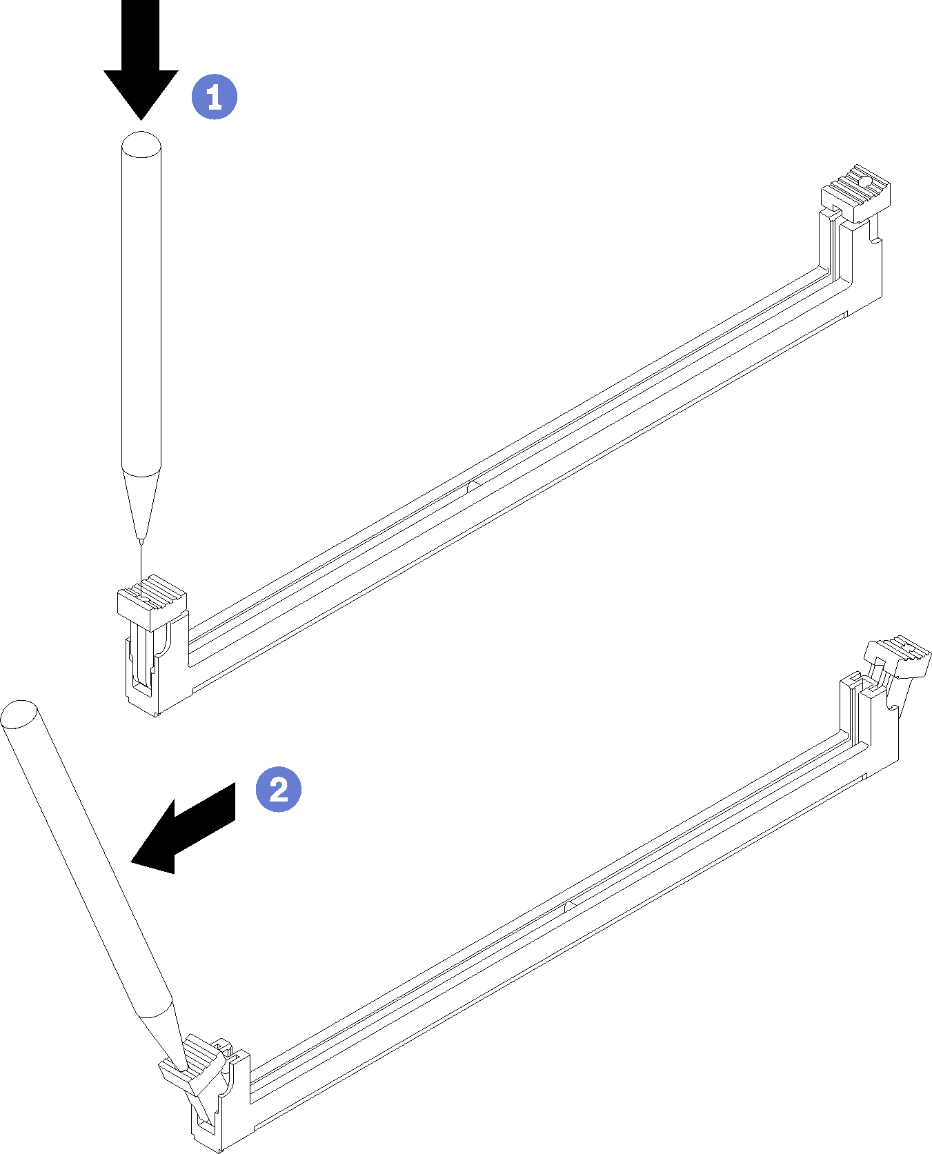
- Remove the DIMM.
- Make sure that the retaining clips are in the fully open position.
- Pull the DIMM out of the connector with both hands.Attention
The retaining clips for adjacent DIMM connectors of processor 1 and processor 2 cannot be open at the same time. Remove or install the DIMMs for each processor one at a time and close the retaining clips after removing a DIMM.
If you are not immediately replacing the DIMM, install the node air baffles (see Install the front air baffle and Install the middle air baffle). The retaining clips on the DIMM connectors must be in the closed position before you install the node air baffles.
Figure 3. DIMM removal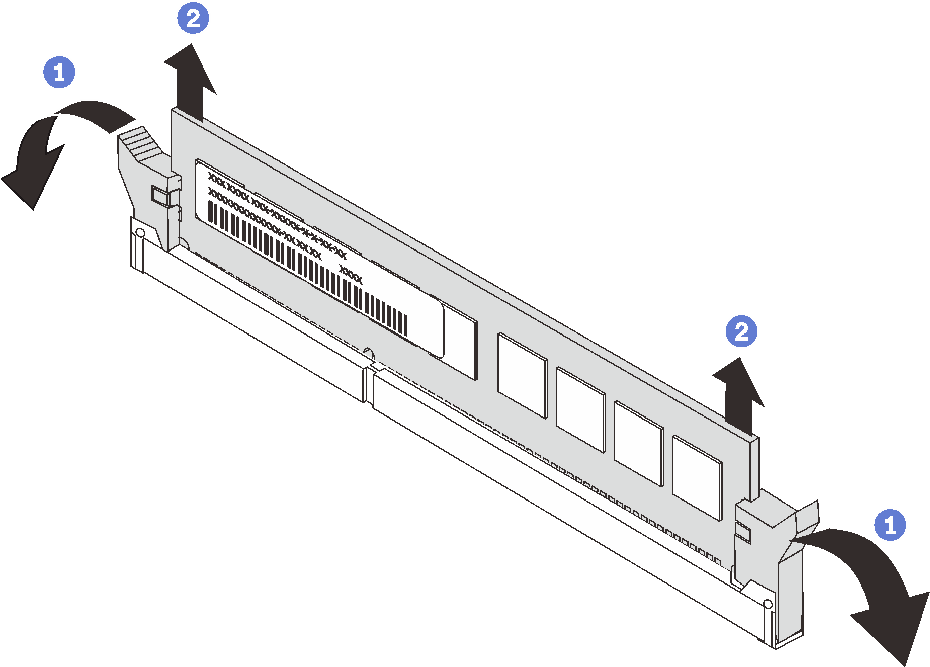
After you finish
If you are instructed to return the component or optional device, follow all of the packaging instructions, and use any packaging materials for shipping that are supplied to you.
Demo video