Remove the water loop
Use this information to remove the water loop in SD650-I V3 tray.
About this task
Required tools
Make sure you have the required tools listed below in hand to properly replace the component.
Water loop kits
SD650-I V3 Water loop service kit (03KH870)
SD650-I V3 Water loop putty pad kit (03LD670)
Conduction plate parts (03KH864) (Only damaged parts needs to be replaced)
M.2 Putty pad kit (03LD666)
Drive gap pad or putty pad kits according to the drives installed in the tray. See their respective replacement procedures for more information.
ConnectX series adapter putty pad kits according to the ConnectX adapter installed in the tray. See their respective replacement procedures for more information.
Screws and screwdrivers
Prepare the following screwdrivers to ensure you can install and remove corresponding screws properly.Screwdriver Type Screw Type Torx T10 head screwdriver Torx T10 screw Torx T30 head screwdriver Torx T30 screw Phillips #1 head screwdriver Phillips #1 screw Phillips #2 head screwdriver Phillips #2 screw
Read Installation Guidelines and Safety inspection checklist to ensure that you work safely.
Turn off the corresponding DWC tray that you are going to perform the task on.
Disconnect all external cables from the enclosure.
Use extra force to disconnect QSFP cables if they are connected to the solution.
To avoid damaging the water loop, always use the water loop carrier when removing, installing or folding the water loop.
| Screwdriver Type | Screw Type |
|---|---|
| Torx T10 head screwdriver | Torx T10 screw |
| Torx T30 head screwdriver | Torx T30 screw |
| Phillips #1 head screwdriver | Phillips #1 screw |
| Phillips #2 head screwdriver | Phillips #2 screw |
Procedure
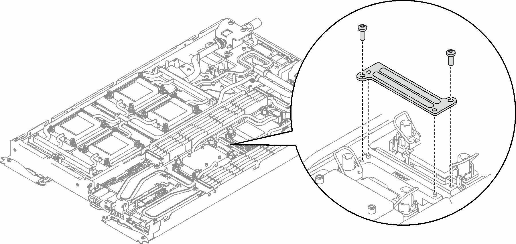
- Remove two Torx T10 screw; then, remove the VR (voltage regulator) clamp plate out of the node.Figure 1. VR clamp plate removal
- Remove the following screws to loosen the quick connect.
Four Torx T10 screws to loosen the quick connect.
Nine Torx T10 screws on the rear of the node.
Figure 2. Quick connect screw removal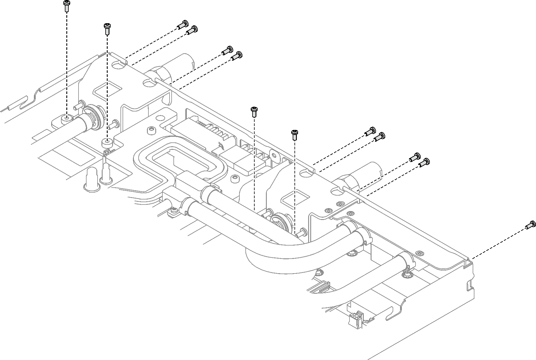
- Remove water loop screws (23x Torx T10 screws for two nodes) with a torque screwdriver set to the proper torque.
14 Torx T10 screws in GPU node.
9 Torx T10 screws in compute node.
NoteFor reference, the torque required for the screws to be fully tightened/removed is 5.0+/- 0.5 lbf-in, 0.55+/- 0.05 N-M.Figure 3. Water loop screws removal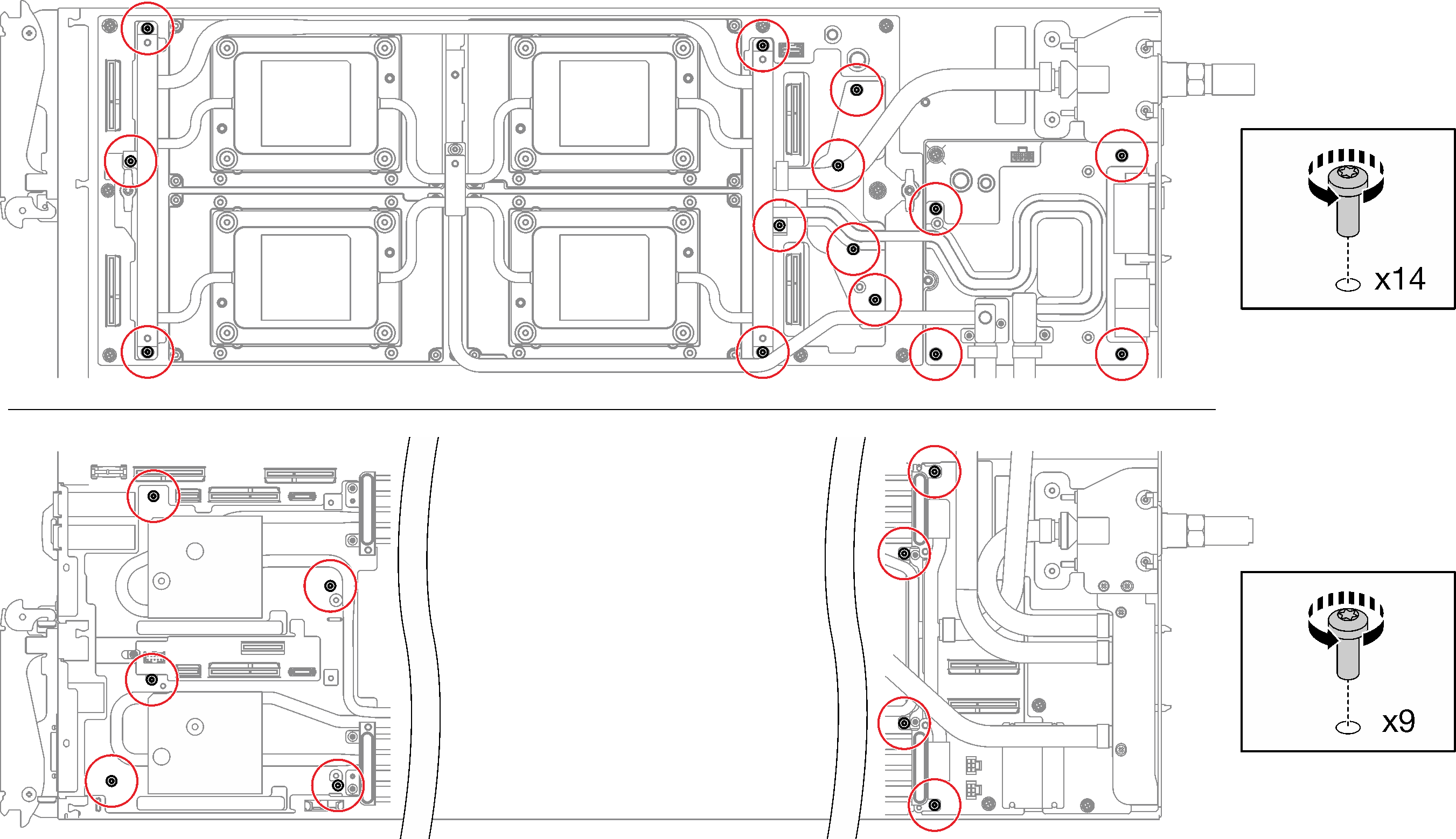
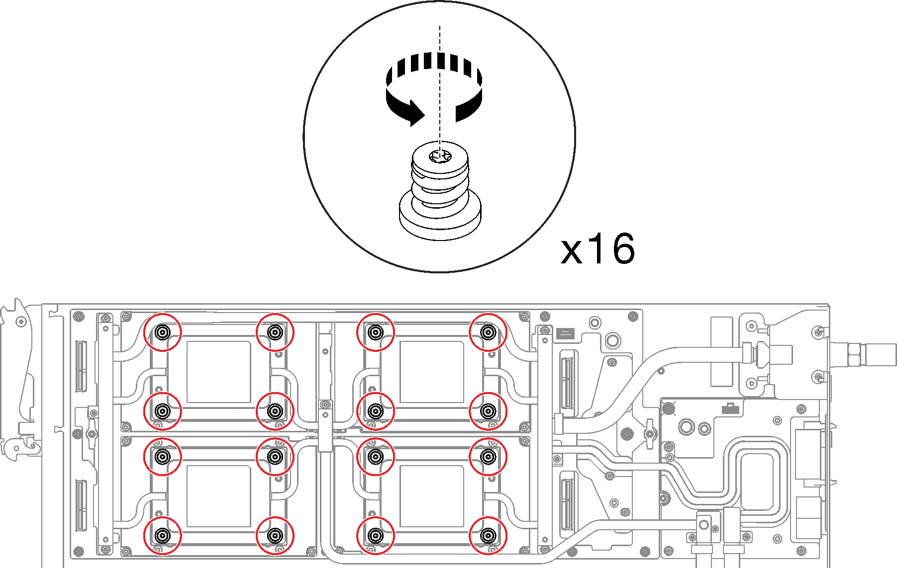
- Remove GPU OAM cold plate screws (16x Torx T15 screws) with a torque screwdriver set to the proper torque.NoteFor reference, the torque required for the screws to be fully tightened/removed is 0.9 +/-0.06 newton-meters, 8+/- 0.5 inch-pounds. The rpm setting is 200 rpm low-speed.Figure 4. GPU OAM cold plate screws removal
- Release the interface plate with a flat head screwdriver.
- There are two notches on the sides of each GPU OAM cold plate for inserting a flat head screwdriver—select the one that is accessible for the flat head screwdriver.Figure 5. Notches on GPU OAM cold plate
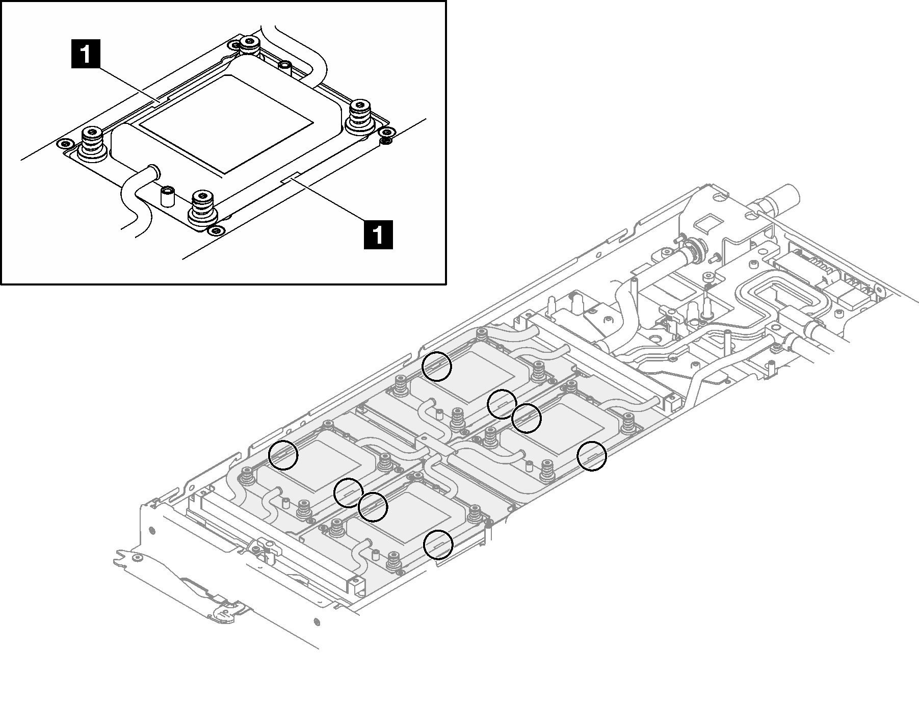
1 Notches - Perform Step B on every GPU OAM cold plate to make sure they are all released from GPU OAM.Figure 6. Release the GPU OAM cold plate from the GPU OAM
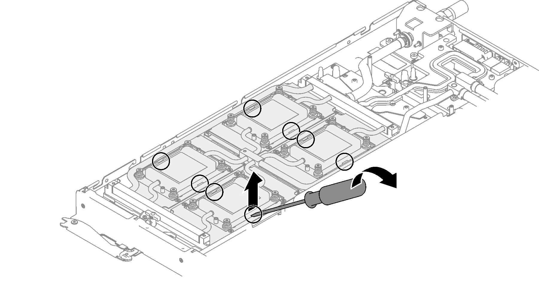
- There are two notches on the sides of each GPU OAM cold plate for inserting a flat head screwdriver—select the one that is accessible for the flat head screwdriver.
- From the front and the rear of the GPU node, find the gaps between the retimer tank on water loop and the carrier base board conduction plate, as shown in the following illustrations. Then, insert the flat head screwdriver into the gaps, and slightly rotate screwdriver to release the two components.Figure 7. Separating water loop retimer tank from carrier base board conduction plate – GPU node front
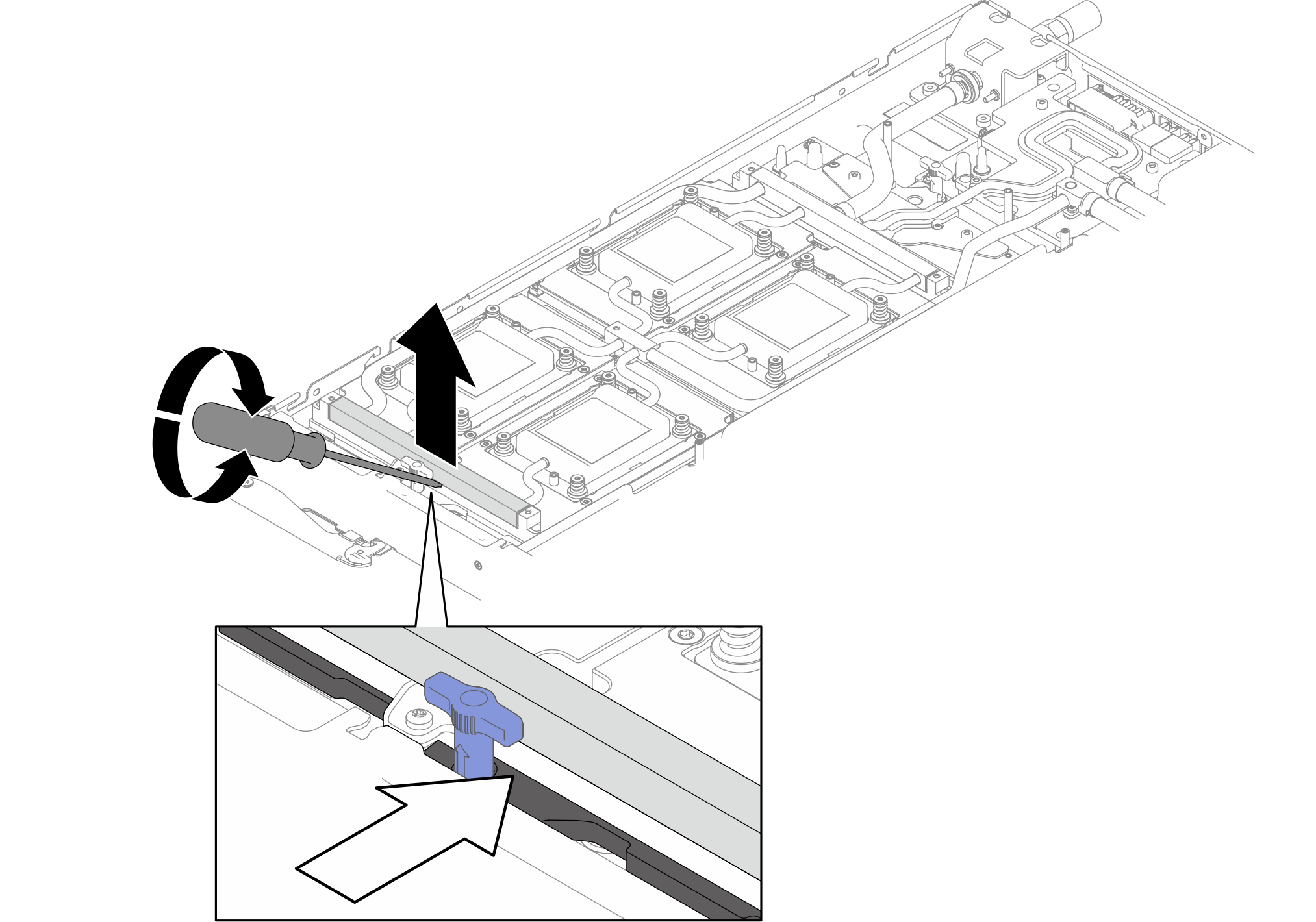 Figure 8. Separating water loop retimer tank from carrier base board conduction plate – GPU node rear
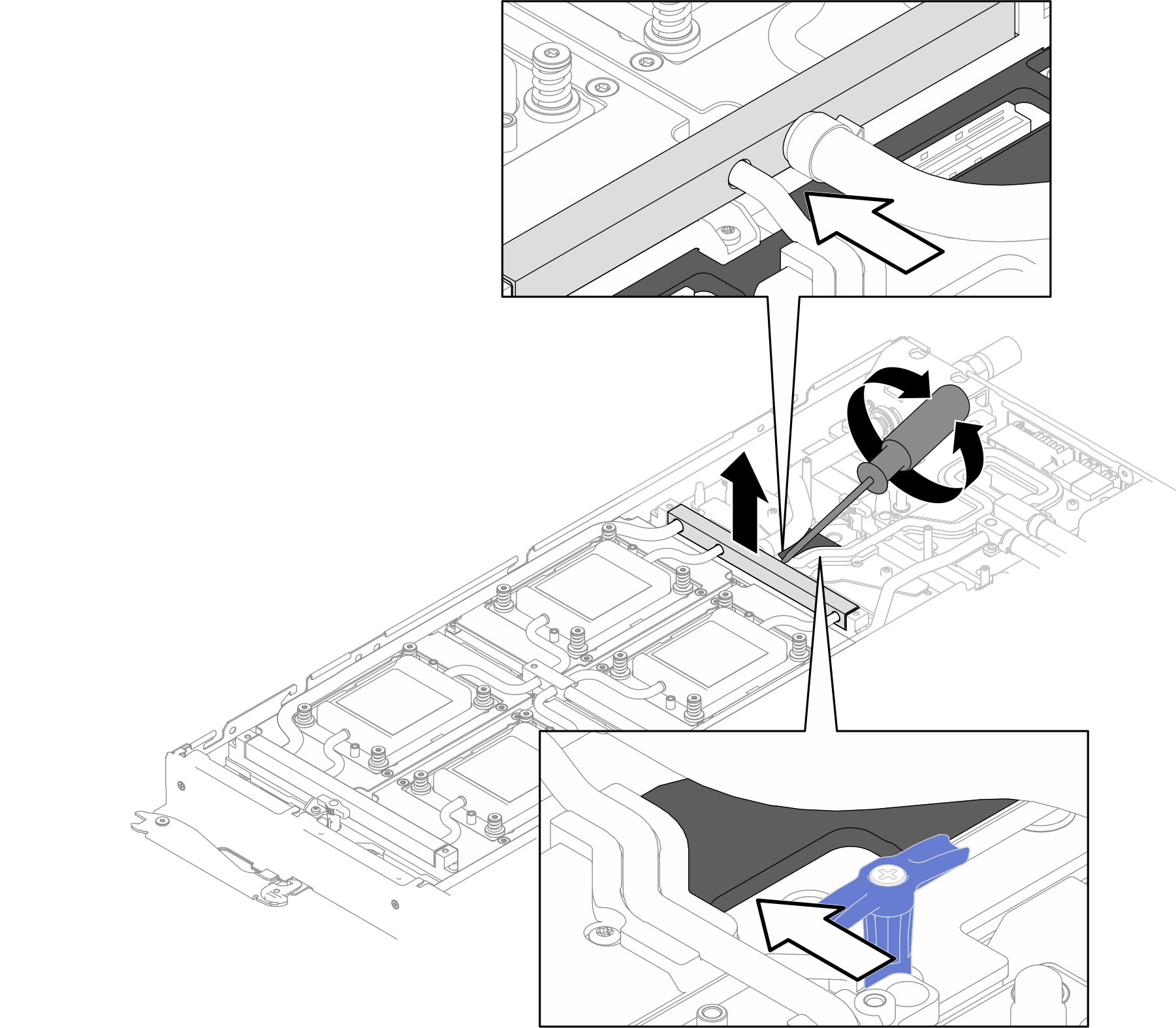
- Loosen processors properly.
 Fully loosen eight Torx T30 captive screws on cold plates in the removal sequence shown on the cold plate label (with a torque screwdriver set to the proper torque).NoteFor reference, the torque required for the screws to be fully tightened/removed is 10+/- 2.0 lbf-in, 1.1+/- 0.2 N-m.AttentionTo prevent damage to components, make sure that you follow the indicated loosening sequence.
 Rotate eight anti-tilt wire bails inwards to the unlocked position.Figure 9. Loosening Torx T30 captive screws
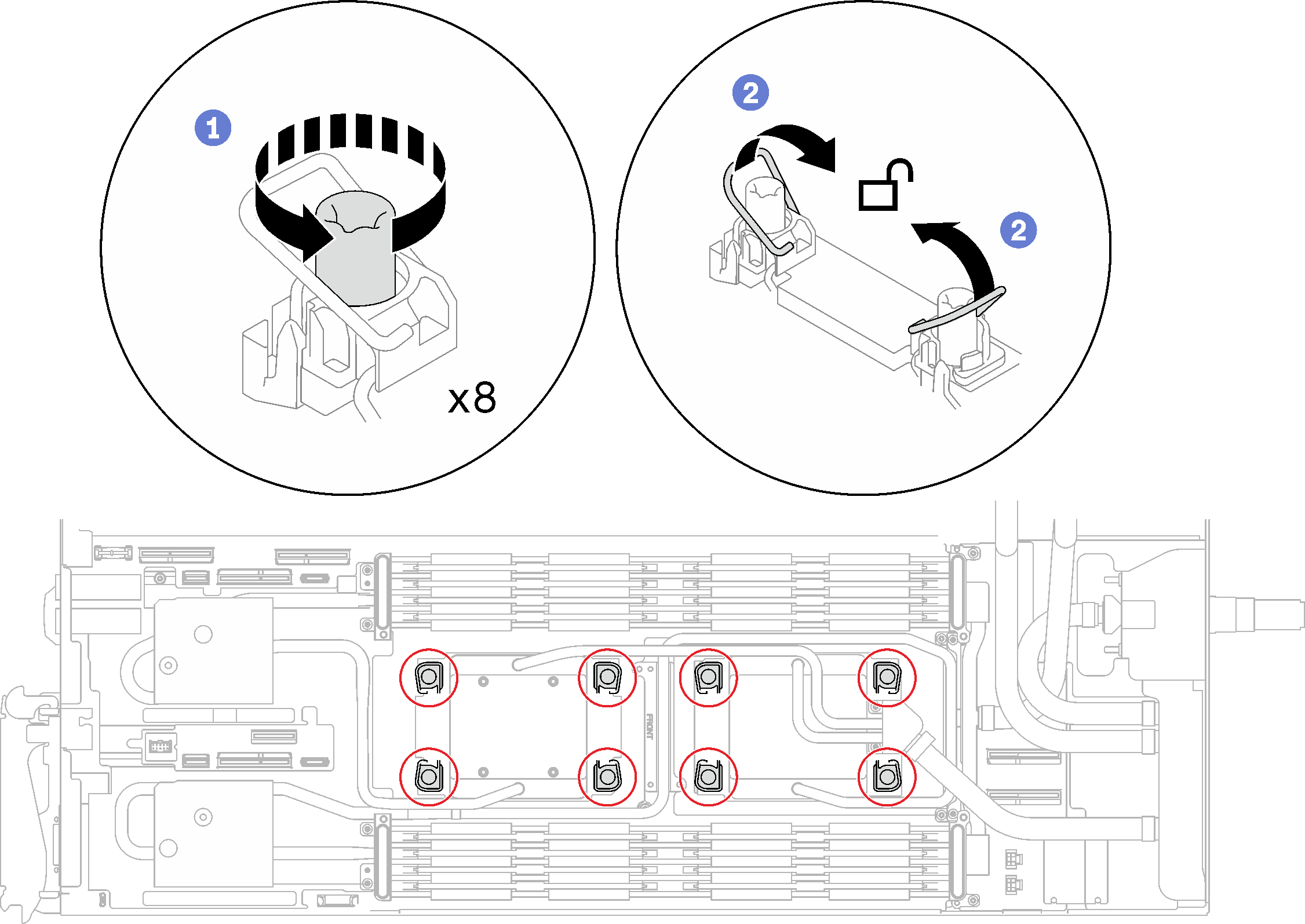
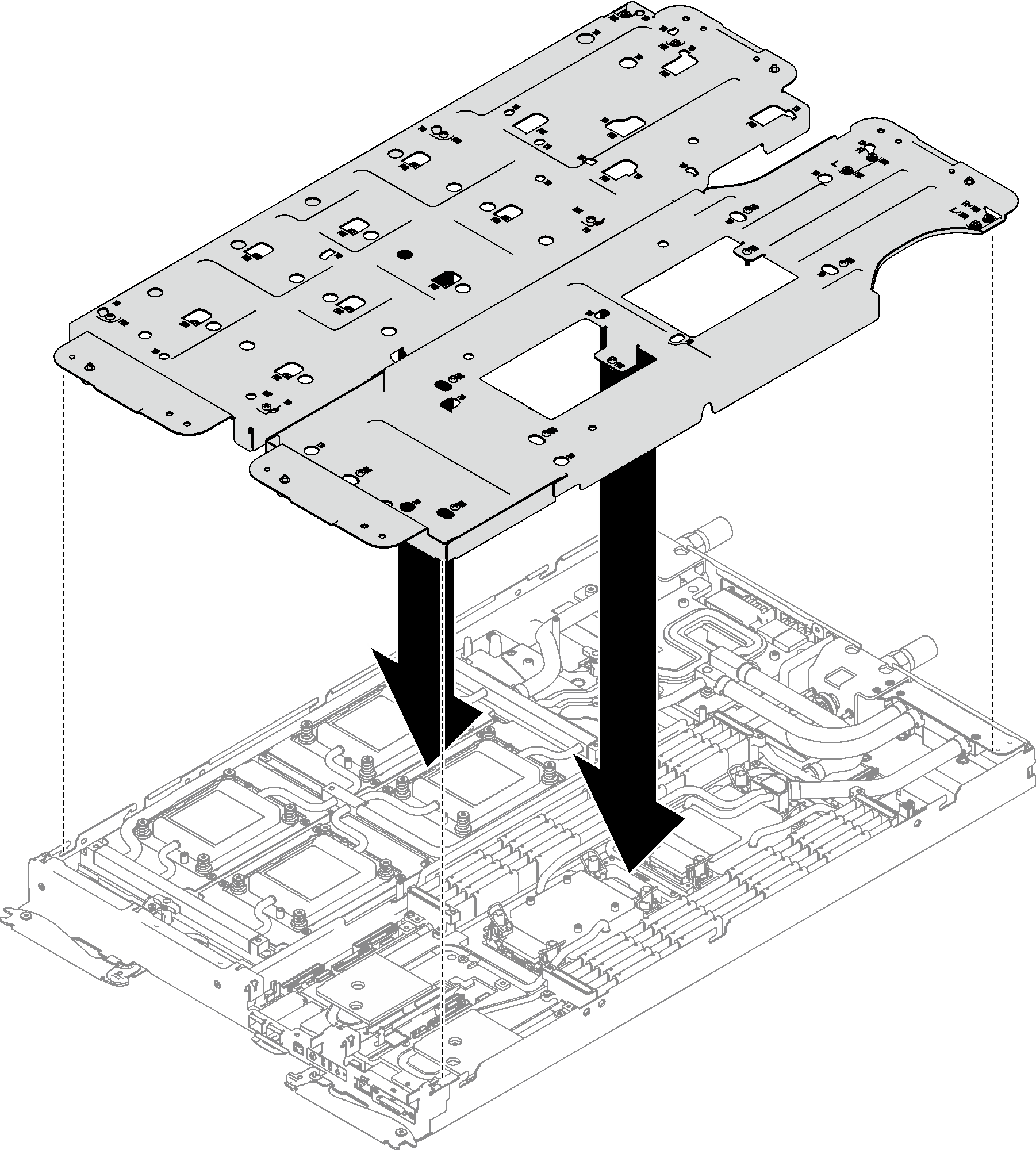
- Orient two water loop carriers with the guide pins; then, gently put two water loop carriers down and ensure they are seated firmly on the water loop.Figure 10. Water loop carrier installation
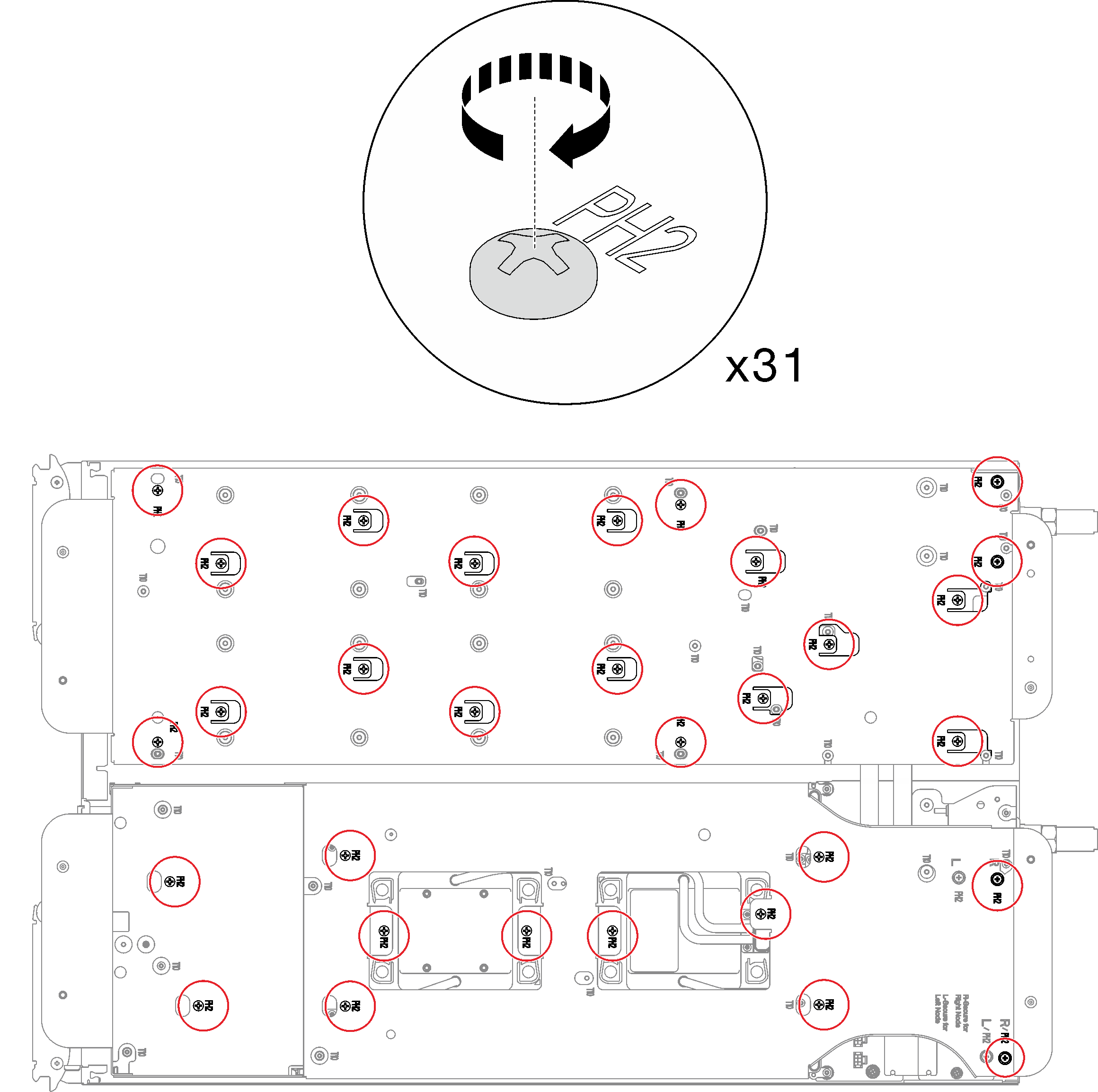
- Tighten water loop carrier screws (31x Phillips #2 screws for two nodes).Figure 11. Water loop carrier screws installation
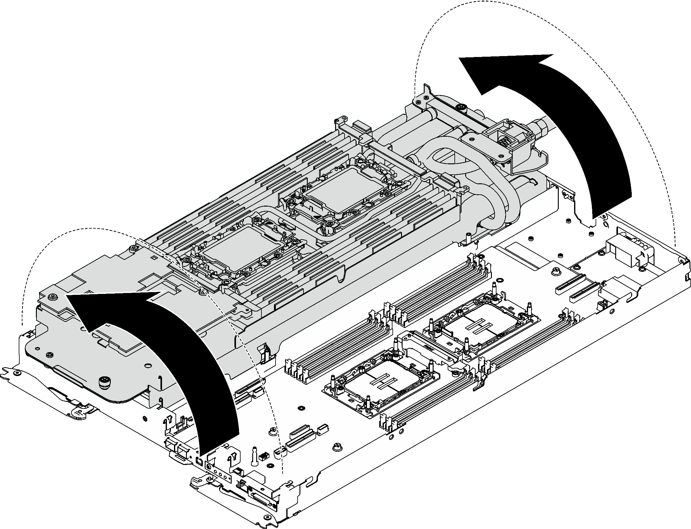
- Carefully rotate the water loop so one half is sitting on top of the other half.Figure 12. Folding the water loop
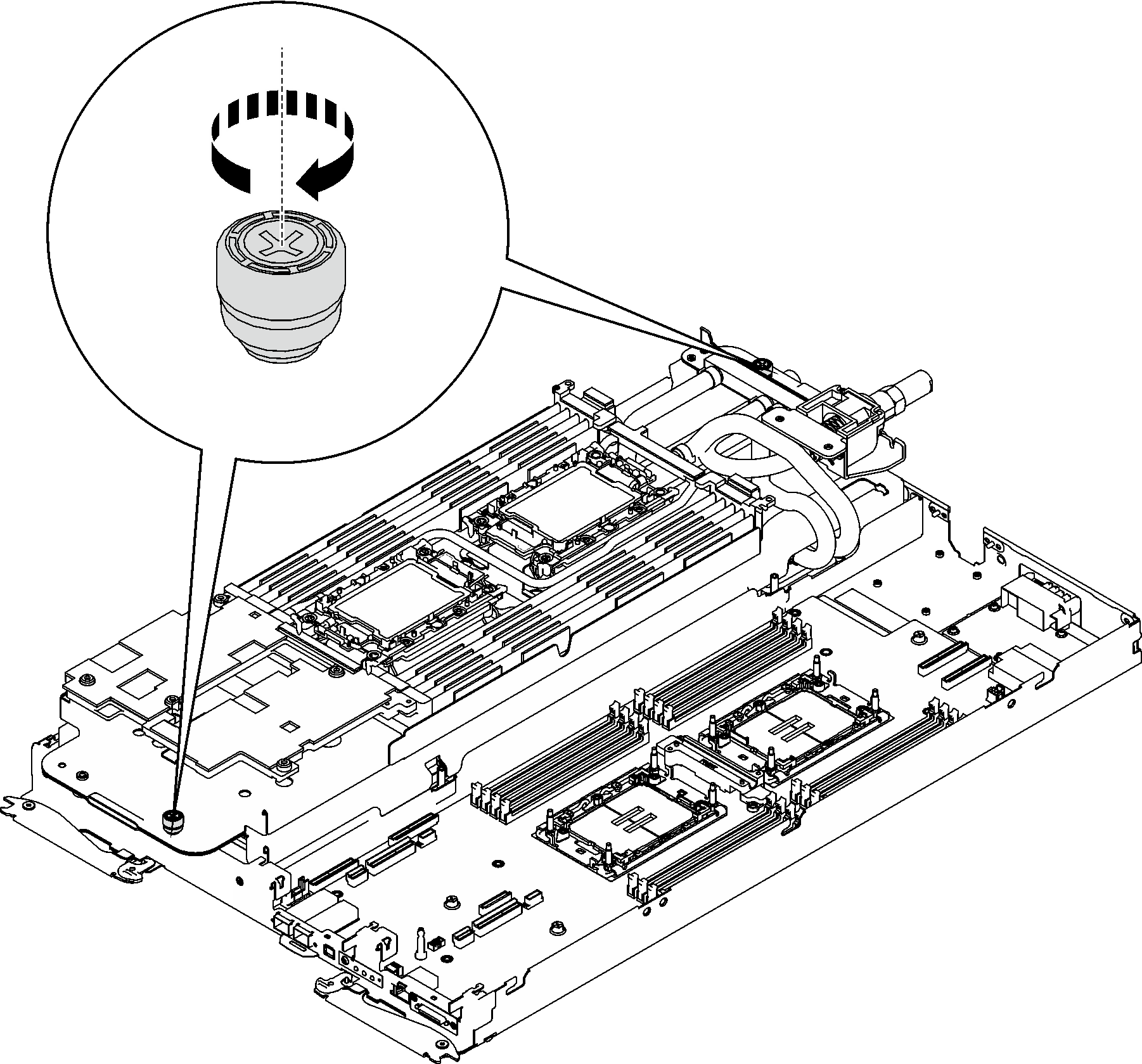
- Fasten two captive thumbscrews to secure water loop carriers to each other.Figure 13. Tightening captive thumbscrews
- Remove the processor from the retainer. This process differs by processor SKU. Check the processor SKU and follow the applicable procedure.NoteDo not touch the contacts on the processor.For non Intel® Xeon® CPU Max processor
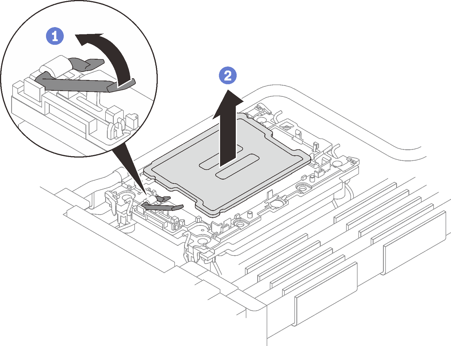
- Lift the handle to release the processor from the retainer.
- Carefully hold the processor by its edges; then, lift the processor from the retainer.Figure 14. Processor removal
For Intel® Xeon® CPU Max processor- Insert a flat head screwdriver into the TIM breaking cam on the retainer; then, slightly rotate the flat head screwdriver to release the processor from the retainer.
- Carefully hold the processor by its edges; then, lift the processor from the retainer.Figure 15. Processor removal (Intel® Xeon® CPU Max processor)
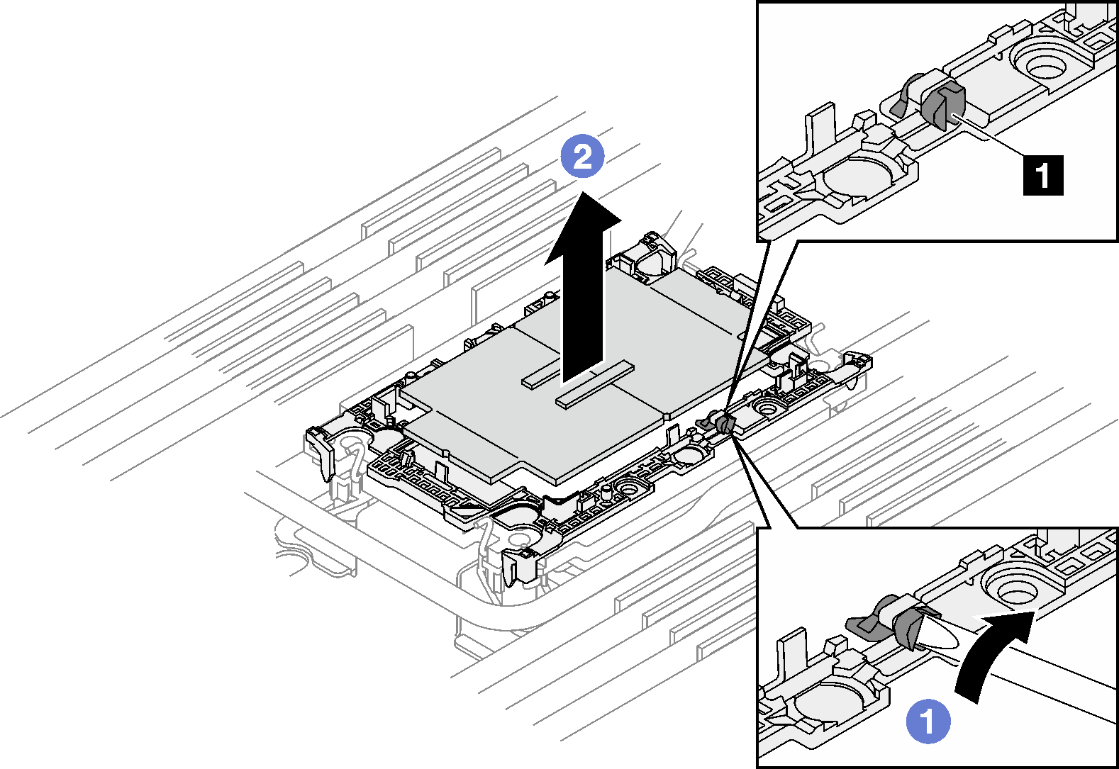
1 TIM breaking cam
- Remove the processor retainer from the underside of the cold plate.NoteThe processor retainer will be discarded and replaced with a new one.
- Carefully release the retaining clips from the cold plate.
- Lift the retainer from the cold plate.
Figure 16. Processor retainer removal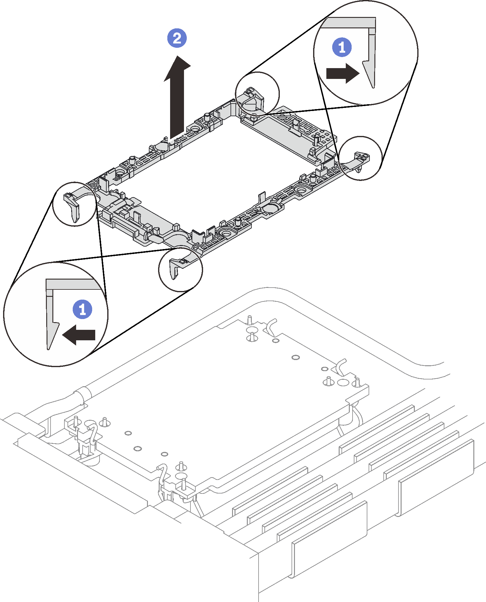
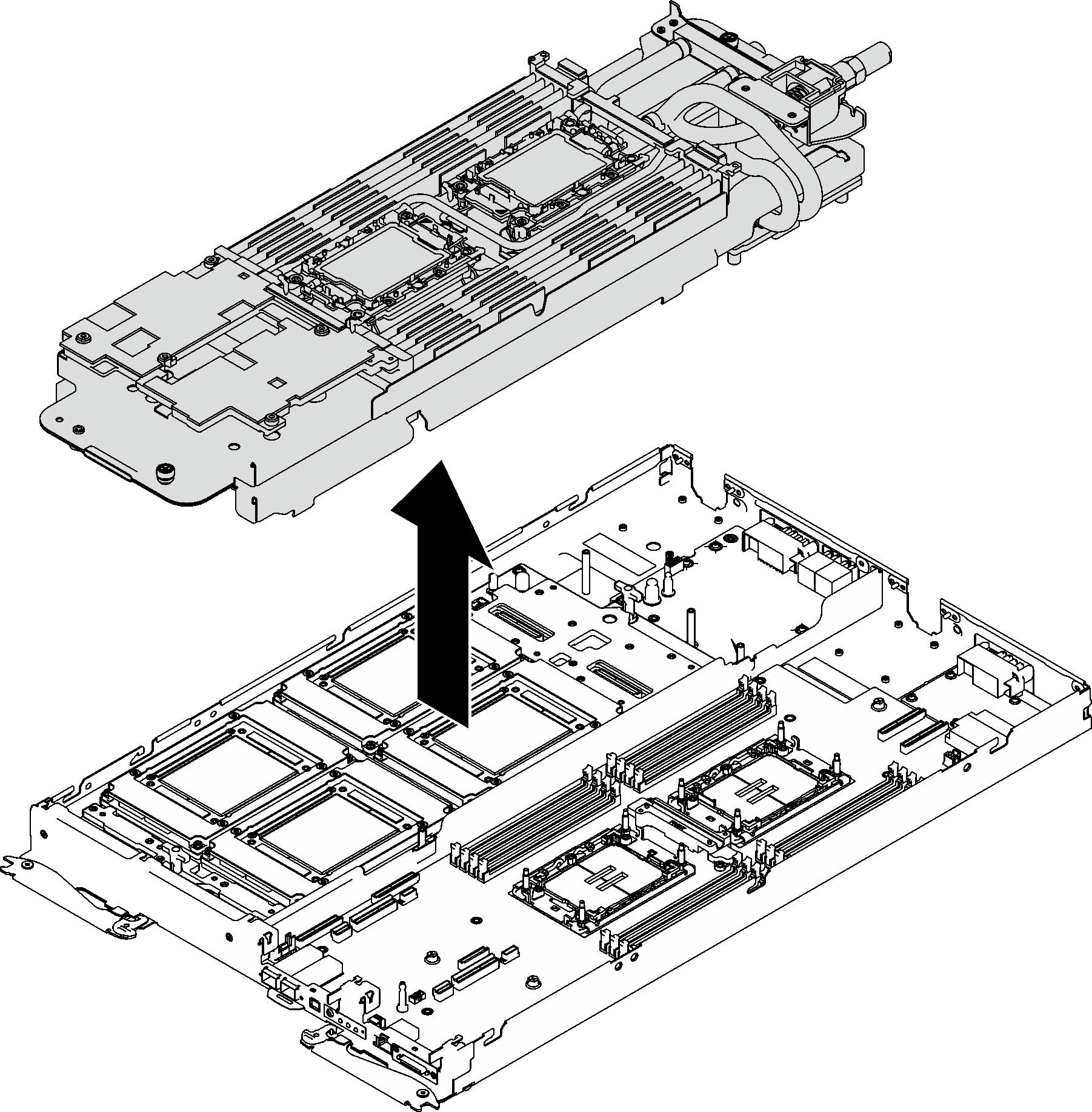
- Carefully lift the water loop out of the node.Figure 17. Water loop removal
If you are instructed to return the component or optional device, follow all packaging instructions, and use any packaging materials for shipping that are supplied to you.
Demo video