Install the water loop
Use this information to install the water loop in SD650-I V3 tray.
Required tools
Make sure you have the required tools listed below in hand to properly replace the component.
Water loop kits
SD650-I V3 Water loop service kit (03KH870)
SD650-I V3 Water loop putty pad kit (03LD670)
Conduction plate parts (03KH864) (Only damaged parts needs to be replaced)
M.2 Putty pad kit (03LD666)
Drive gap pad or putty pad kits according to the drives installed in the tray. See their respective replacement procedures for more information.
ConnectX series adapter putty pad kits according to the ConnectX adapter installed in the tray. See their respective replacement procedures for more information.
Screws and screwdrivers
Prepare the following screwdrivers to ensure you can install and remove corresponding screws properly.Screwdriver Type Screw Type Torx T10 head screwdriver Torx T10 screw Torx T30 head screwdriver Torx T30 screw Phillips #1 head screwdriver Phillips #1 screw Phillips #2 head screwdriver Phillips #2 screw
About this task
Read Installation Guidelines and Safety inspection checklist to ensure that you work safely.
Turn off the corresponding DWC tray that you are going to perform the task on.
Disconnect all external cables from the enclosure.
Use extra force to disconnect QSFP cables if they are connected to the solution.
To avoid damaging the water loop, always use the water loop carrier when removing, installing or folding the water loop.
After updating XCC firmware, perform virtual reseat via SMM2 to optimize system, see SMM2 User Guide.
To identify the gap pad/putty pad location and orientation, see Gap pad and putty pad identification and location.
Before replacing the gap pad/putty pad, gently clean the interface plate or the hardware surface with an alcohol cleaning pad.
Hold the gap pad/putty pad carefully to avoid deformation. Make sure no screw hole or opening is blocked by the gap pad/putty pad material.
Do not use expired putty pad. Check the expiry date on putty pad package. If the putty pads are expired, acquire new ones to properly replace them.
Procedure
- Follow the following steps if you are replacing processors:
- Apply the thermal grease on the top of the processor with syringe by forming four uniformly spaced dots, while each dot consists of about 0.1 ml of thermal greaseNoteCarefully place the processor and retainer on a flat surface with the processor-contact side down.Figure 1. Thermal grease application
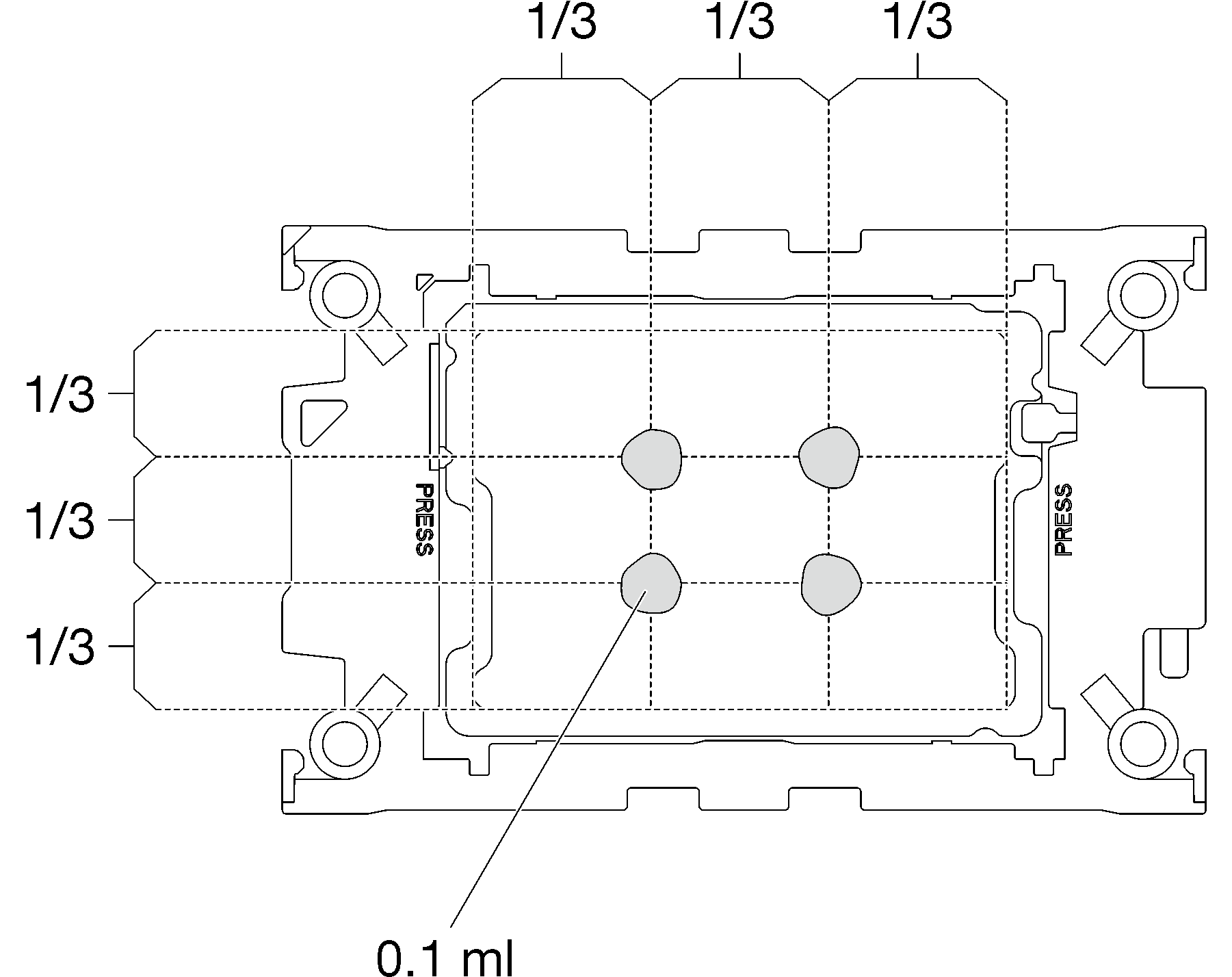
- Apply the thermal grease on the top of the processor with syringe by forming four uniformly spaced dots, while each dot consists of about 0.1 ml of thermal grease
- Install processor retainers onto processor if needed.
- Gently place the processor retainer on the processor; then, carefully press the four sides of the processor retainer to secure the processor.Figure 2. Installing a processor retainer
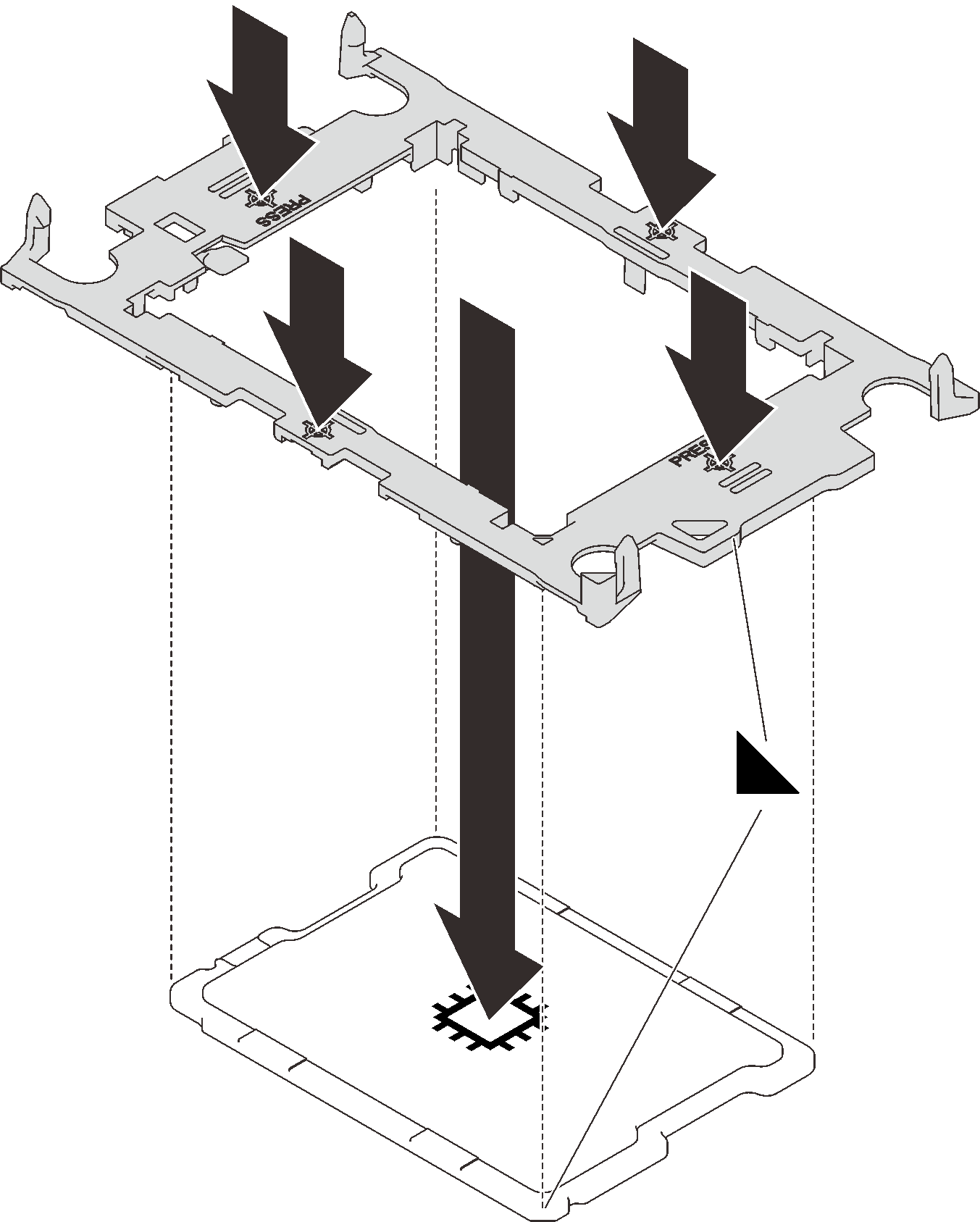 Figure 3. Installing a Intel® Xeon® CPU Max processor retainer
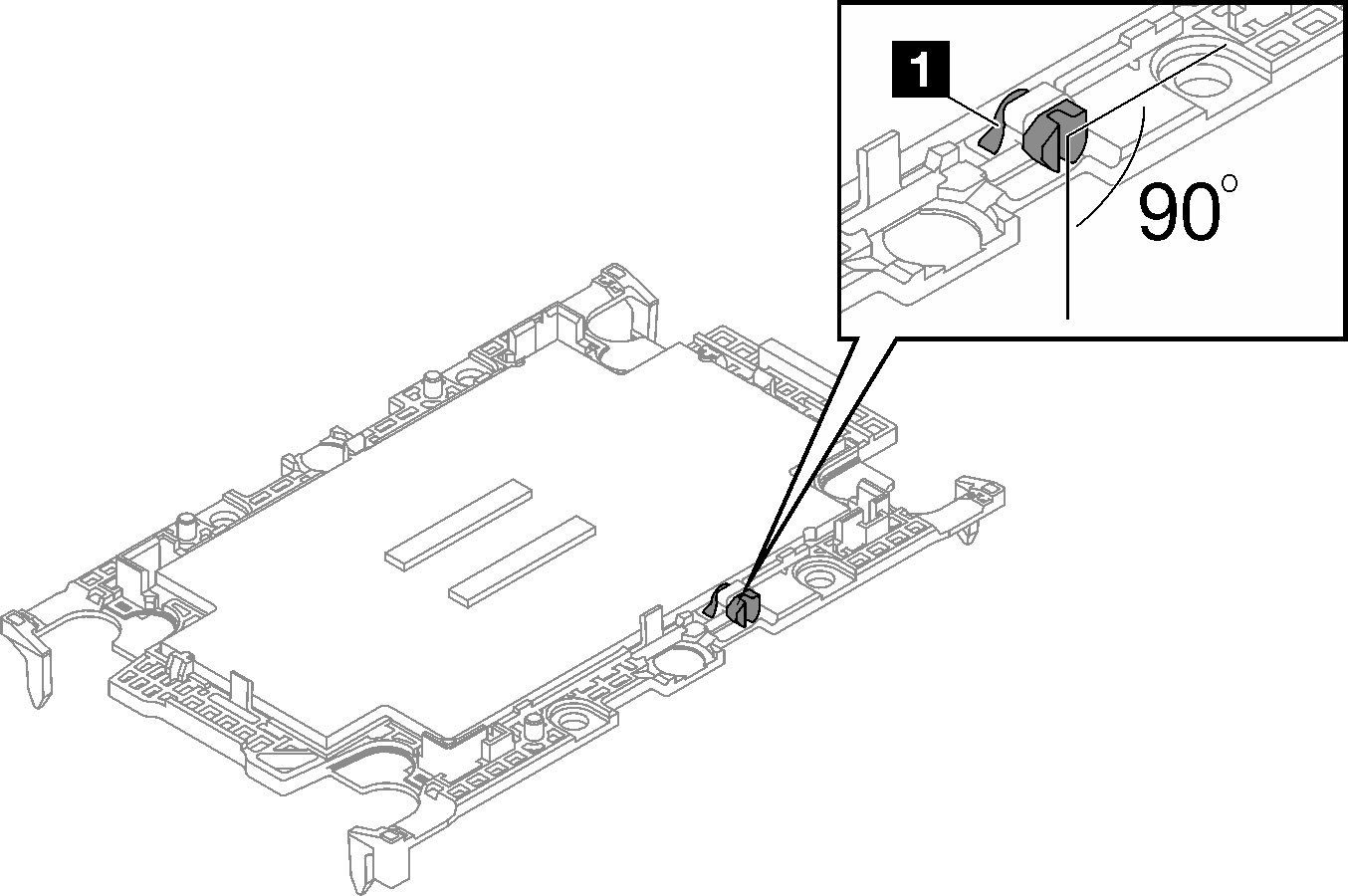
1 TIM breaking cam

- (Intel® Xeon® CPU Max only) After installing the retainer onto processor, make sure the slot on the TIM breaking cam is vertical.Figure 4. TIM breaking cam on processor retainer
1 TIM breaking cam
- Gently place the processor retainer on the processor; then, carefully press the four sides of the processor retainer to secure the processor.
- When removing the water loop from the package box, make sure to hold the touch points marked in grey in the illustration below.AttentionHolding the water loop anywhere other than the touch points may cause damage to it.Figure 5. Touching points when removing water loop from package box
Top image Isometric view of water loop Bottom image Top view of the water loop 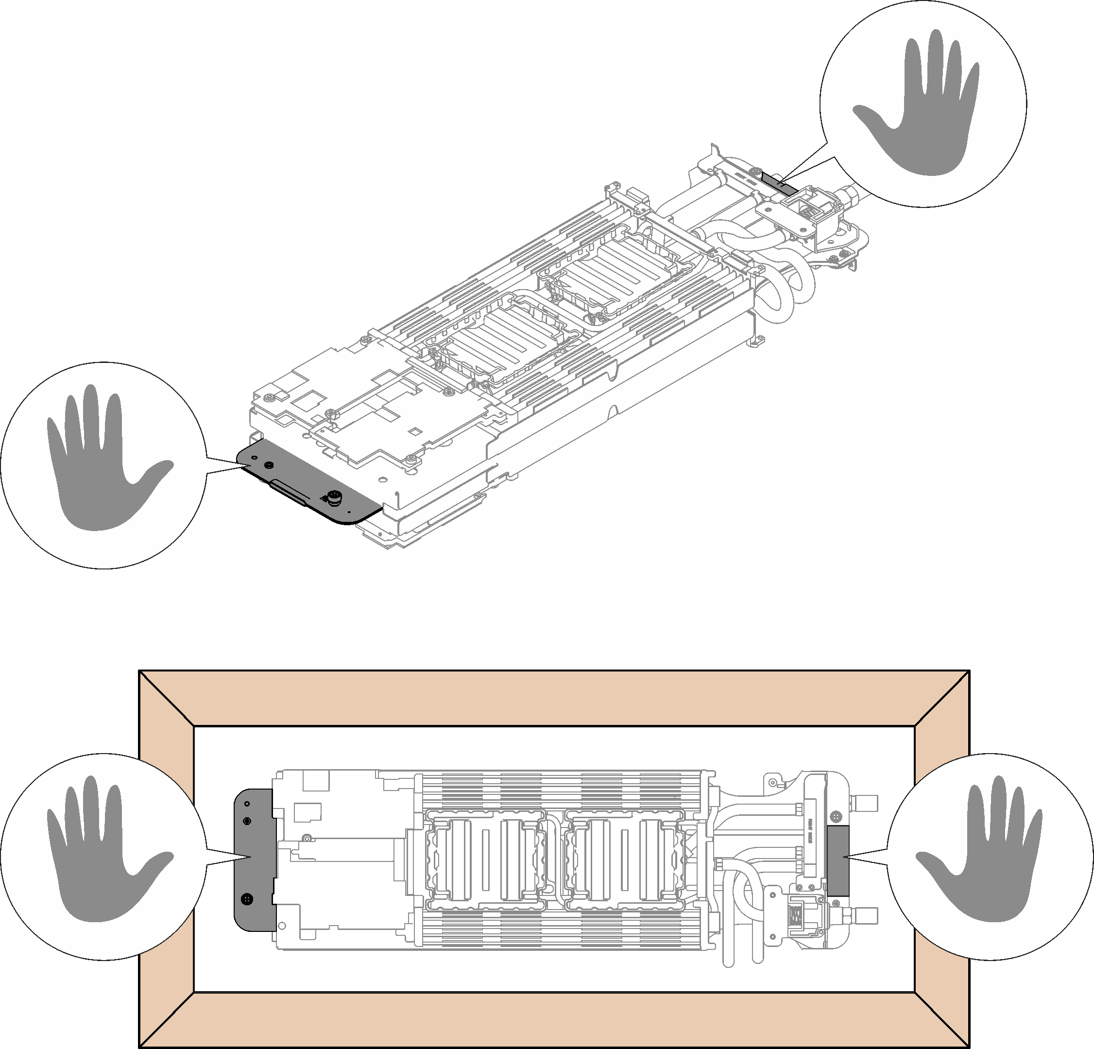
- Remove two plastic grease covers if needed.
 Use a pair of scissors to cut off the tape.
 Remove plastic grease covers from the underside of water loop cold plates.
NoteThe right node is shown as example. Remove plastic grease covers if needed when installing processor in either node.Figure 6. Plastic grease covers removal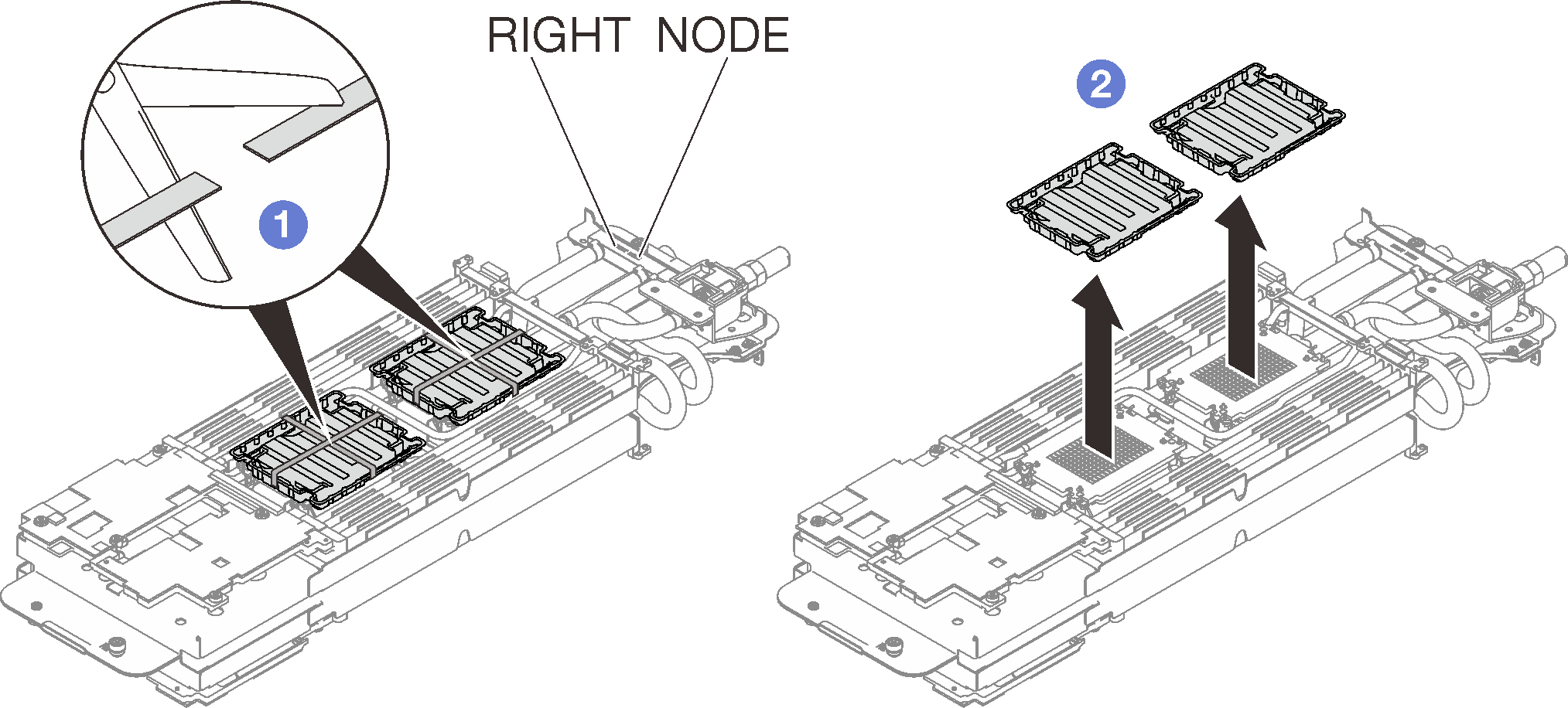
- Align the triangular marks on the processor retainers with the triangular slots on the underside of the water loop cold plate; then, attach the processors to the underside of the water loop cold plate by inserting the processor retainer posts and clips features into the openings at the four corners of the cold plate.Figure 7. Processor installation

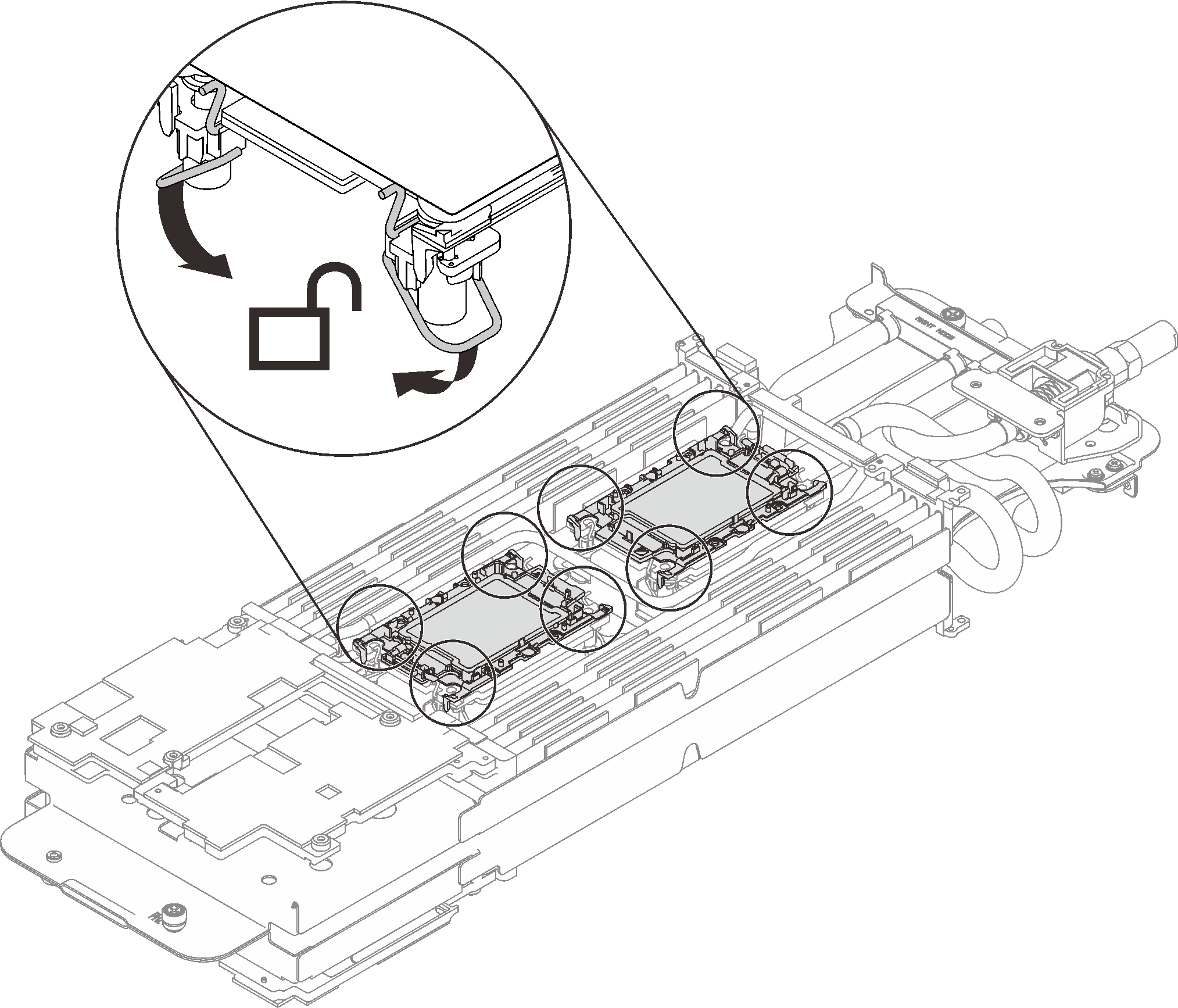
- Rotate all anti-tilt wire bails (8x anti-tilt wire bails per node) outwards to the unlocked position.Figure 8. Processor unlocked position
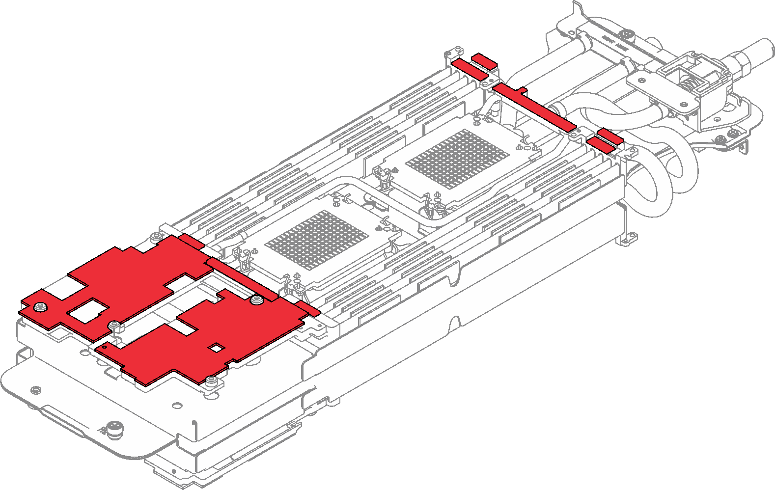
- Check the gap pads on the water loop, if any of them are damaged or detached, replace them with the new ones.Figure 9. Water loop gap pads
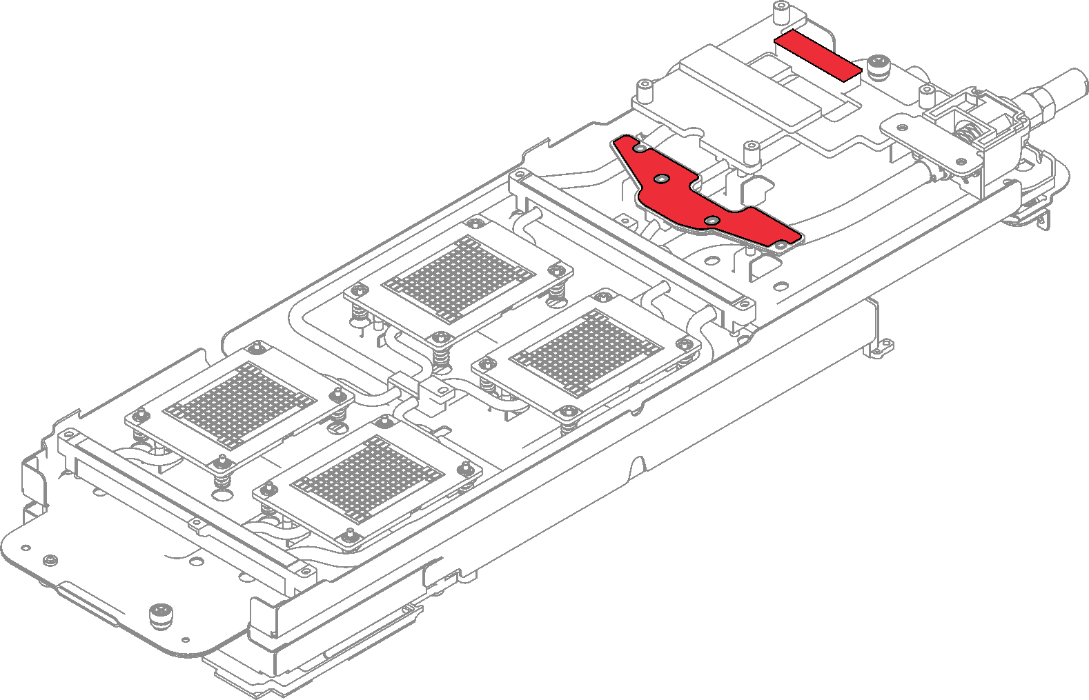
- Check the gap pads on the water loop, if any of them are damaged or detached, replace them with new ones. Make sure to follow Gap pad/putty pad replacement guidelines.Figure 10. Gap pad locations
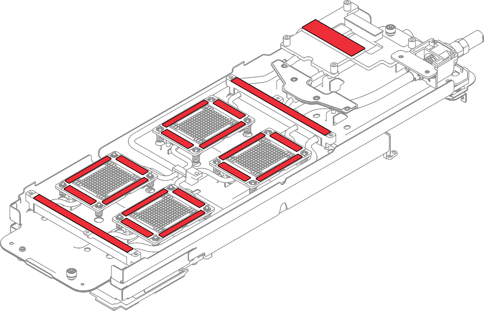
- Replace the putty pads on the water loop with new ones. Make sure to follow Gap pad/putty pad replacement guidelines.NoteWhen attaching the putty pads on GPU cold plate, align the putty pads with the markings on the GPU cold plate.Figure 11. Putty pad locations
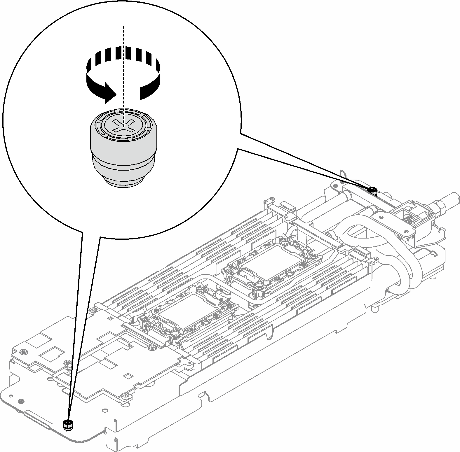
- Fully loosen two captive thumbscrews located at each end of the water loop carrier.Figure 12. Loosening captive thumbscrews
- Install the one side of the water loop.
- Carefully hold the water loop and flip it.
- Carefully position the water loop onto the two guide pins near the rear of the node; then, gently lower down the water loop and ensure it is seated firmly on the system board.
Figure 13. Water loop carrier installation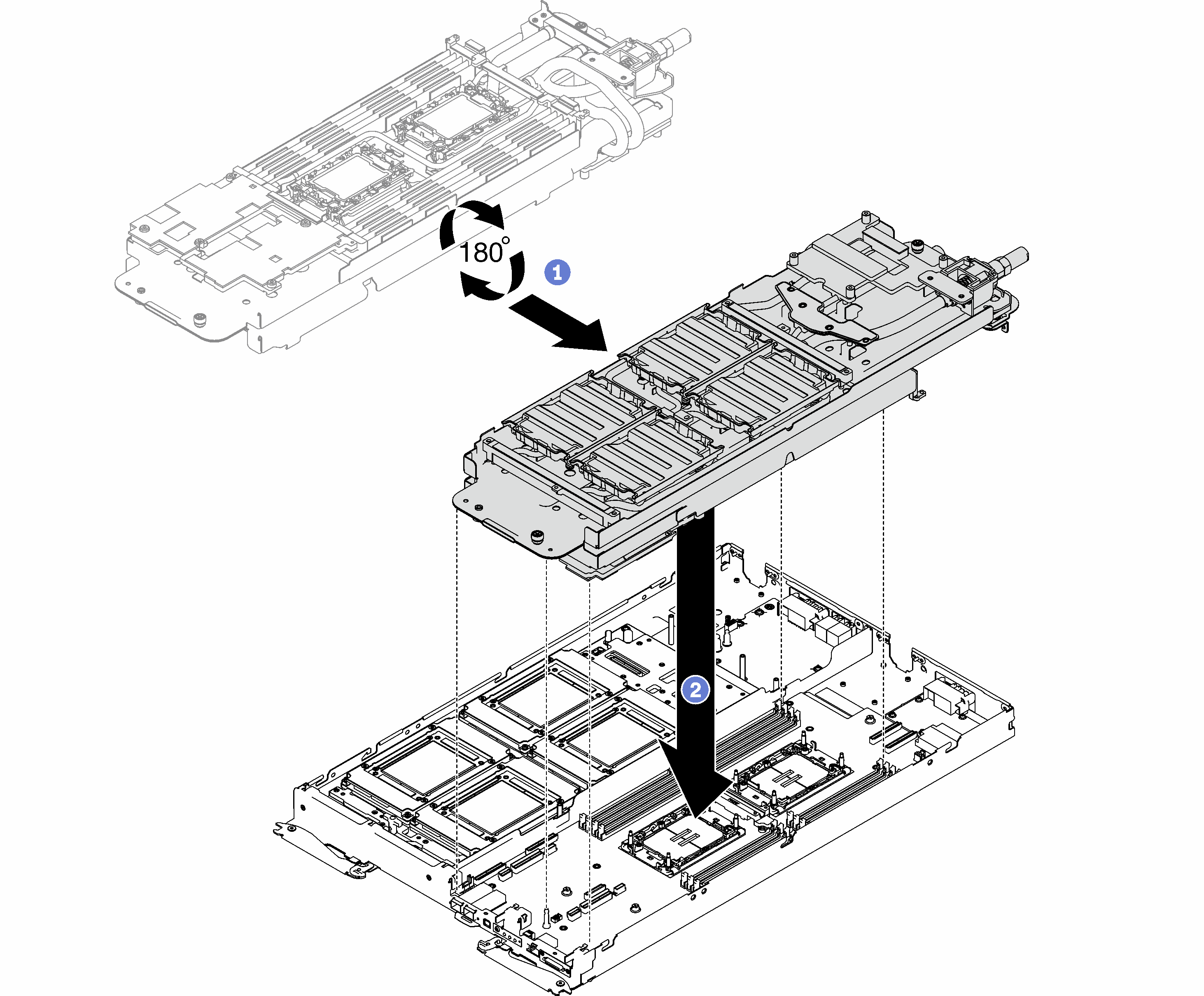
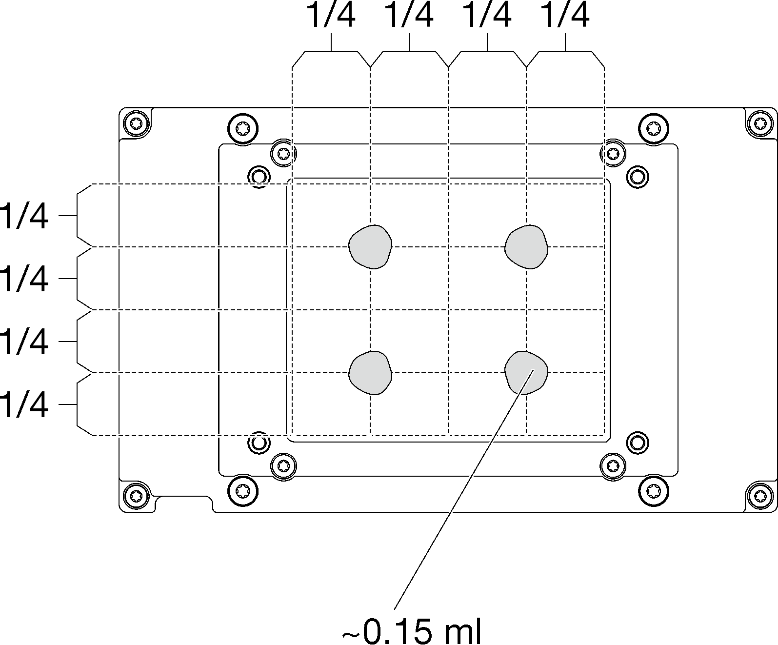
- Apply the thermal grease on the top of the four GPU OAMs with syringe by forming four dots spaced as shown, while each dot consists of about 0.15 ml of thermal grease.Figure 14. Thermal grease application
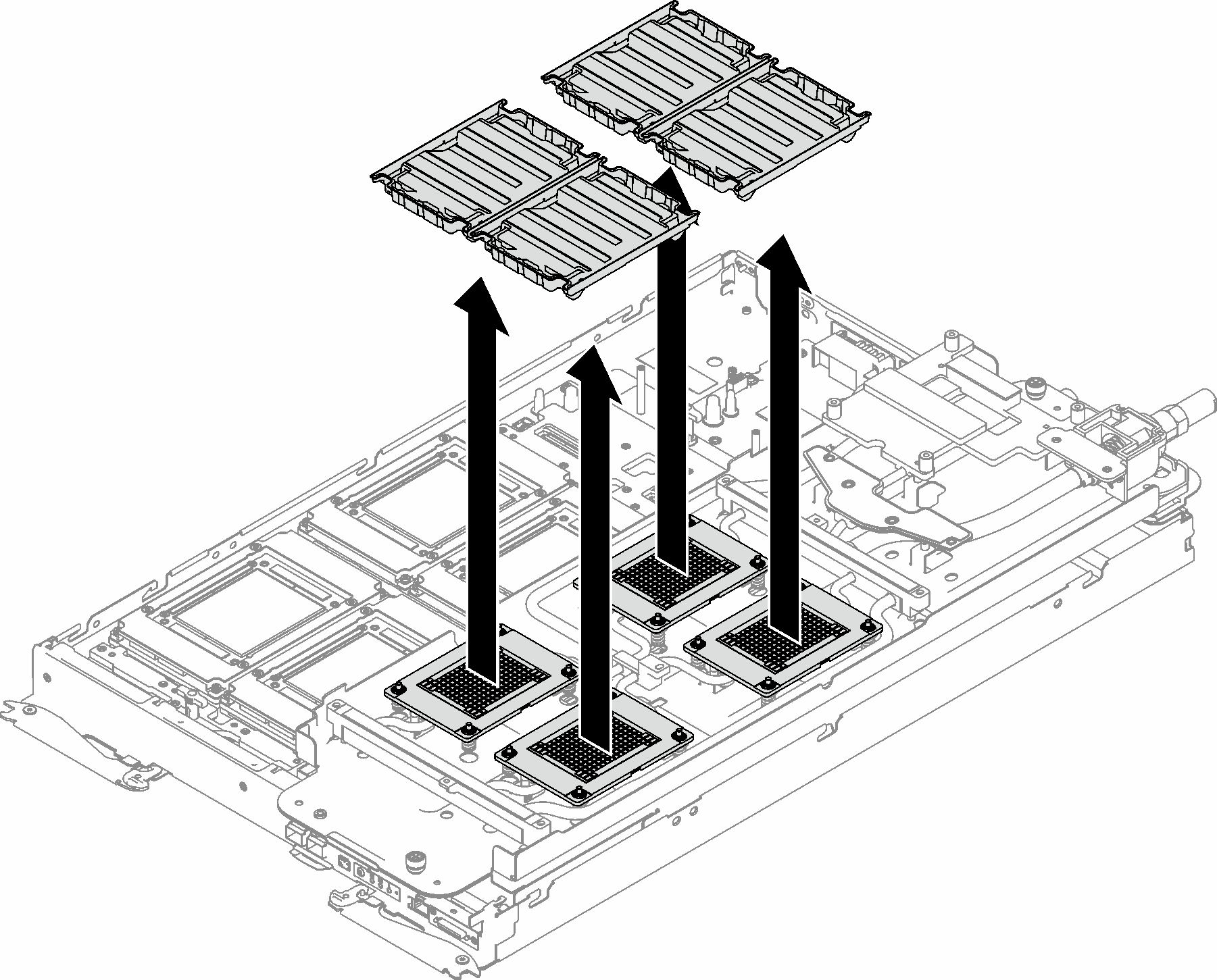
- Remove all plastic grease covers from underside of water loop cold plates.Figure 15. Plastic grease covers removal
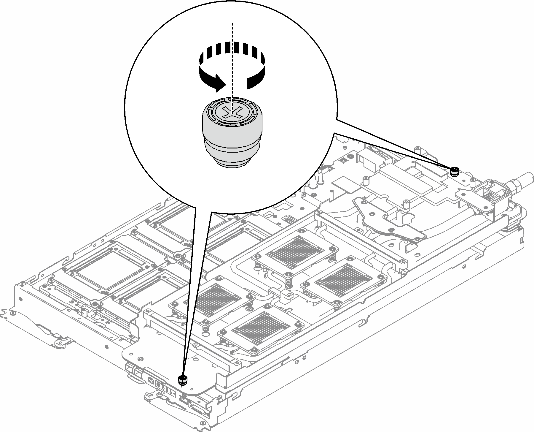
- Fully loosen two captive thumbscrews located at each end of the water loop carrier.Figure 16. Loosening captive thumbscrews
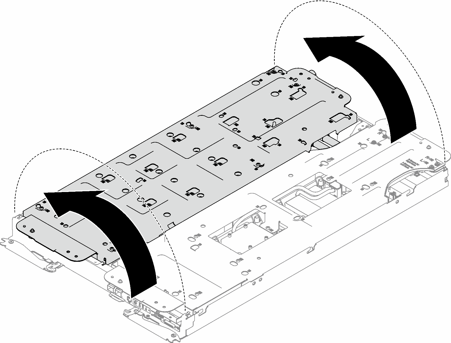
- Unfold and install the other side of the water loop as shown.Figure 17. Unfolding water loop
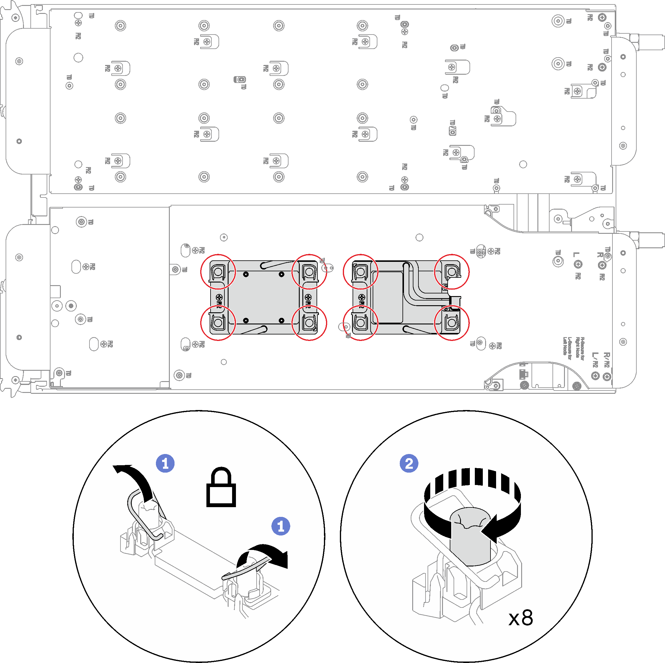
- Ensure the processors are secured properly.
- Rotate anti-tilt wire bails (8x anti-tilt wire bails) outwards to the locked position.
- Fully tighten all Torx T30 captive screws (8x Torx T30 captive screws) on cold plates in the installation sequence shown on the cold plate label (with a torque screwdriver set to the proper torque).NoteFor reference, the torque required for the screws to be fully tightened/removed is 10+/- 2.0 lbf-in, 1.1+/- 0.2 N-m.AttentionTo prevent damage to components, make sure that you follow the indicated tightening sequence.Figure 18. Securing Torx T30 captive screws
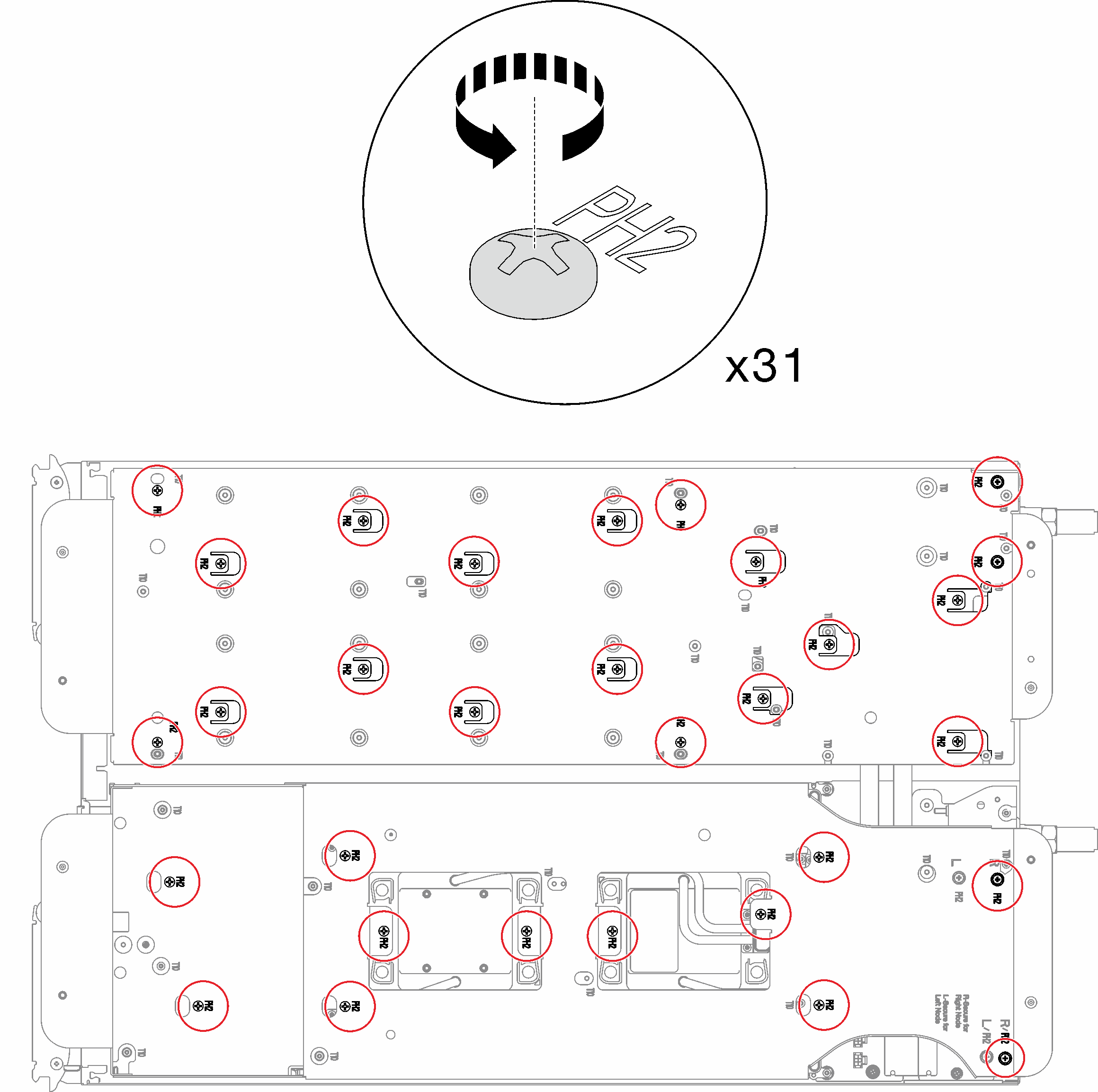
- Loosen water loop carrier screws (31x Phillips #2 screws for two nodes).Figure 19. Loosening water loop carrier screws
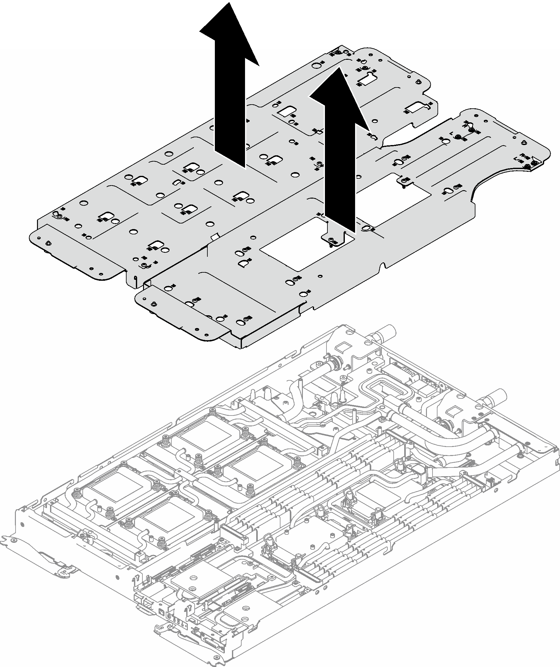
- Carefully lift each water loop carrier up and away from the water loop one at a time.Figure 20. Water loop carrier removal
- Install water loop screws with a torque screwdriver sets to the proper torque.
14 Torx T10 screws in GPU node.
9 Torx T10 screws in compute node.
NoteFor reference, the torque required for the screws to be fully tightened/removed is 5.0+/- 0.5 lbf-in, 0.55+/- 0.05 N-M.Figure 21. Water loop screws installation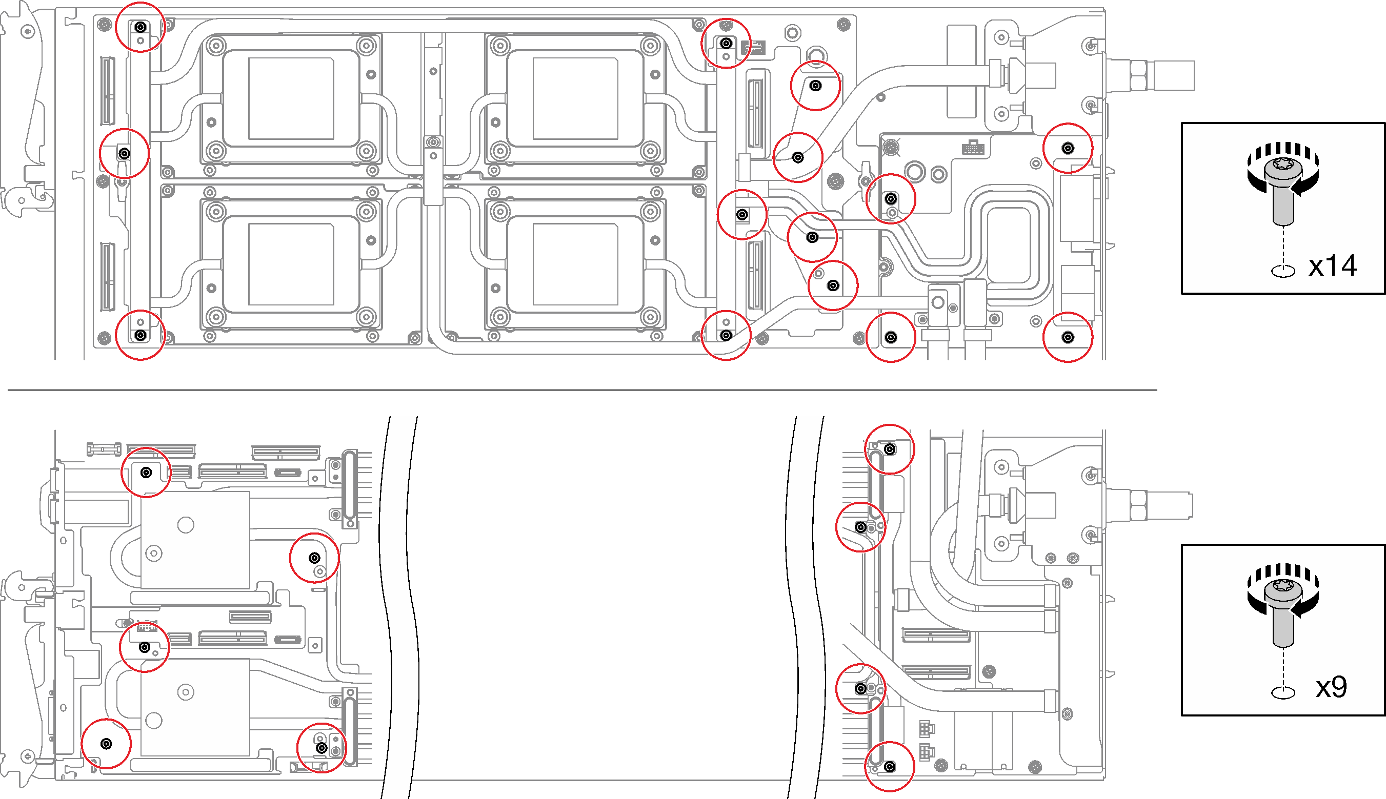
- Install the following screws to secure the quick connect.
Four Torx T10 screws to loosen the quick connect.
Nine Torx T10 screws on the rear of the node.
Figure 22. Quick connect screw installation
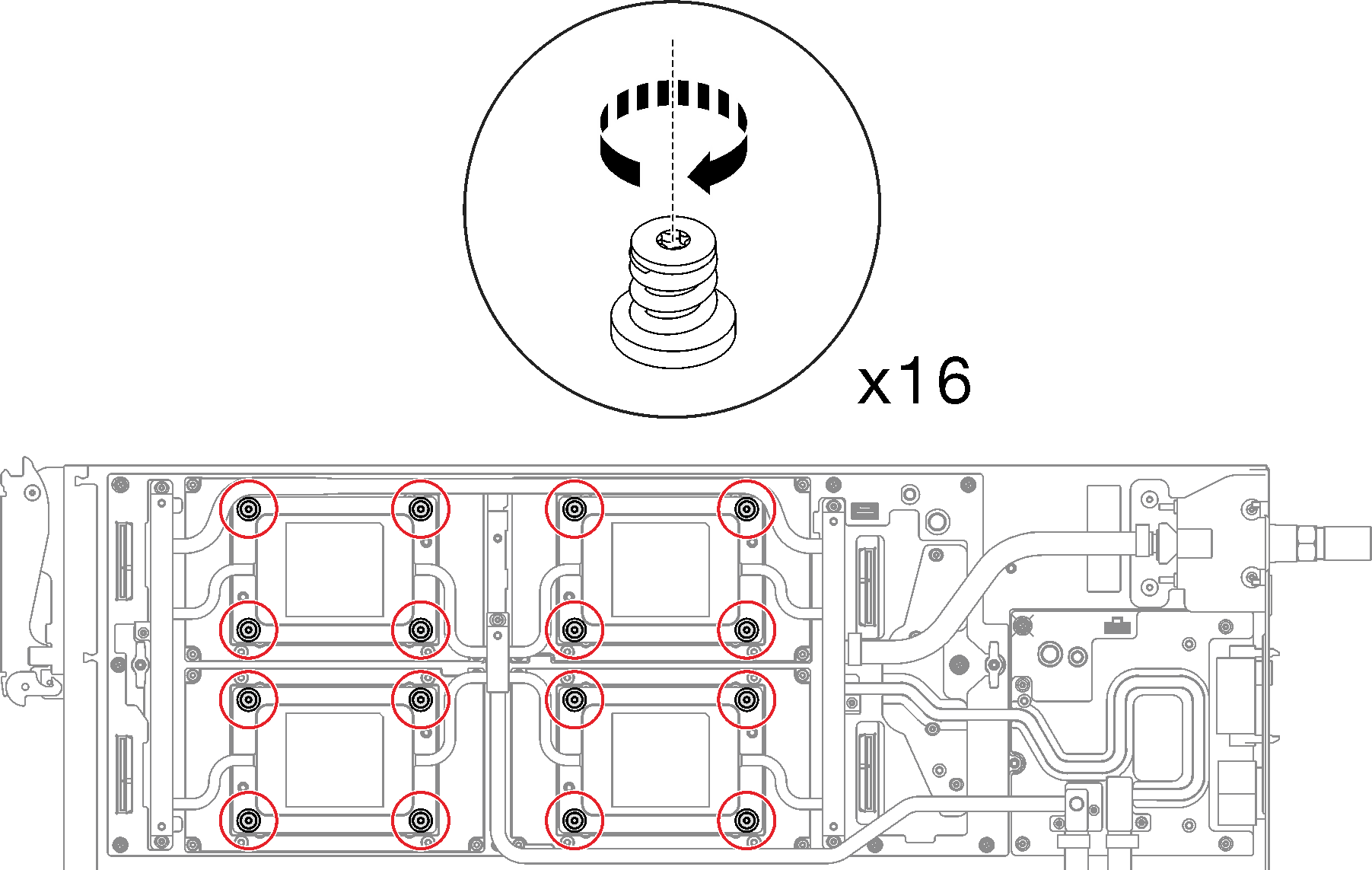
- Install the GPU OAM cold plate screws (16x Torx 15 screws).Figure 23. GPU OAM cold plate screw installation
- Push down the GPU OAM cold plate with your palm to reduce the gap between the GPU OAM cold plate and the GPU OAM.
- Press the torque screwdriver against the screw so that the screw is engaged with the GPU OAM.
 Follow the screw sequence specified on the GPU OAM cold plate label, and fasten each screw for 720 degrees with a torque screwdriver set to the proper torque and rpm.NoteFor reference, the torque required for the screws to be fully tightened/removed is 0.9 +/-0.06 newton-meters, 8+/- 0.5 inch-pounds. The rpm setting is 200 rpm low-speed.Figure 24. Fastening GPU OAM cold plate screws for 720 degrees
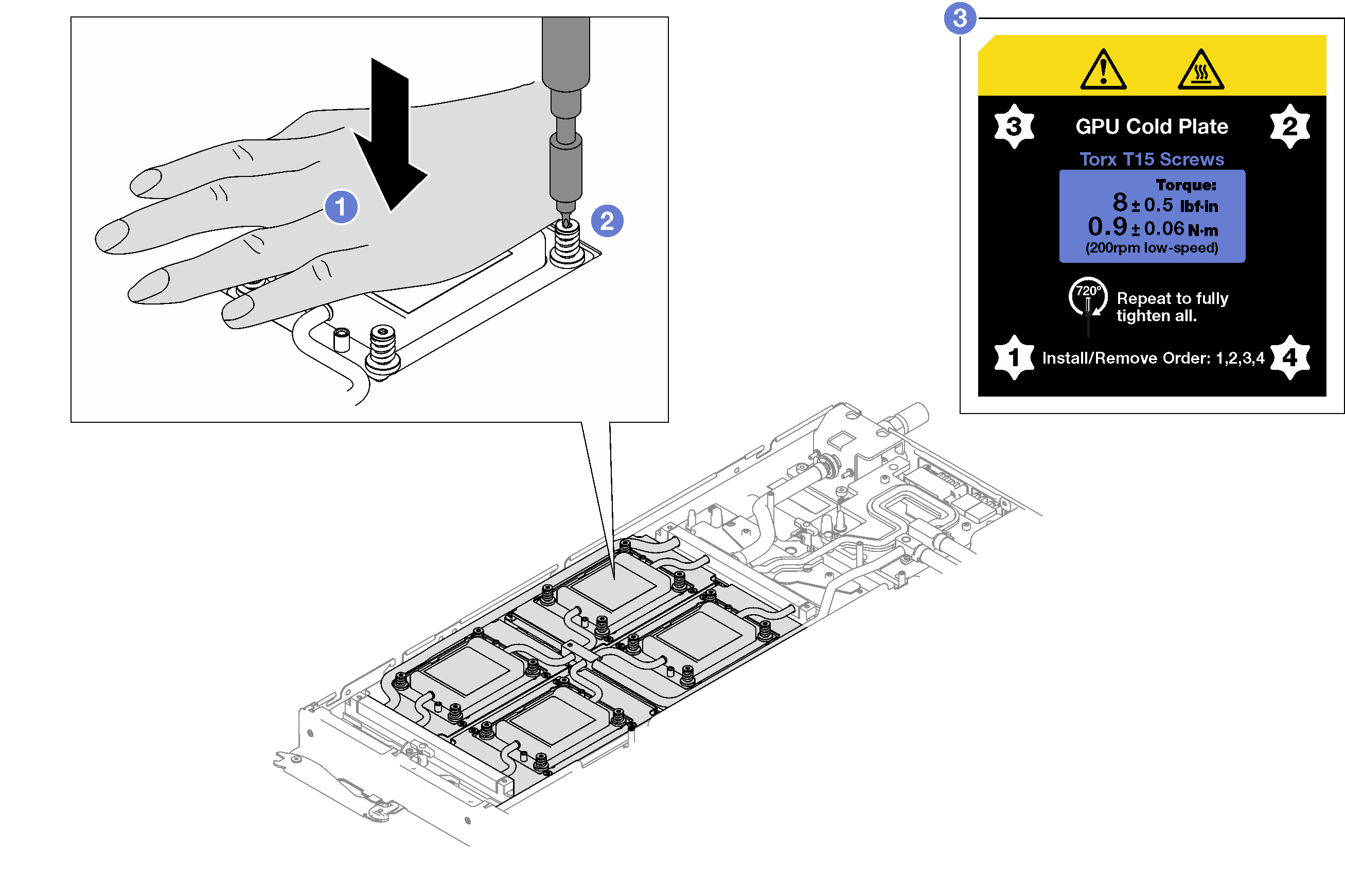
 Make sure that the GPU OAM cold plate is lowered into the node and its surface is flat without tilting. If the GPU OAM cold plate is tilted, unfasten the screws, and repeat Step 1 to Step 3.
 Repeat Step 3 until the screws are fully tightened.
-
 Make sure the height of each screw is 11.5±0.3 millimeter (0.45±0.01 inch) and is fully compressed. If not, repeat the GPU OAM cold plate installation steps.Figure 25. Height of properly installed GPU OAM cold plate screw
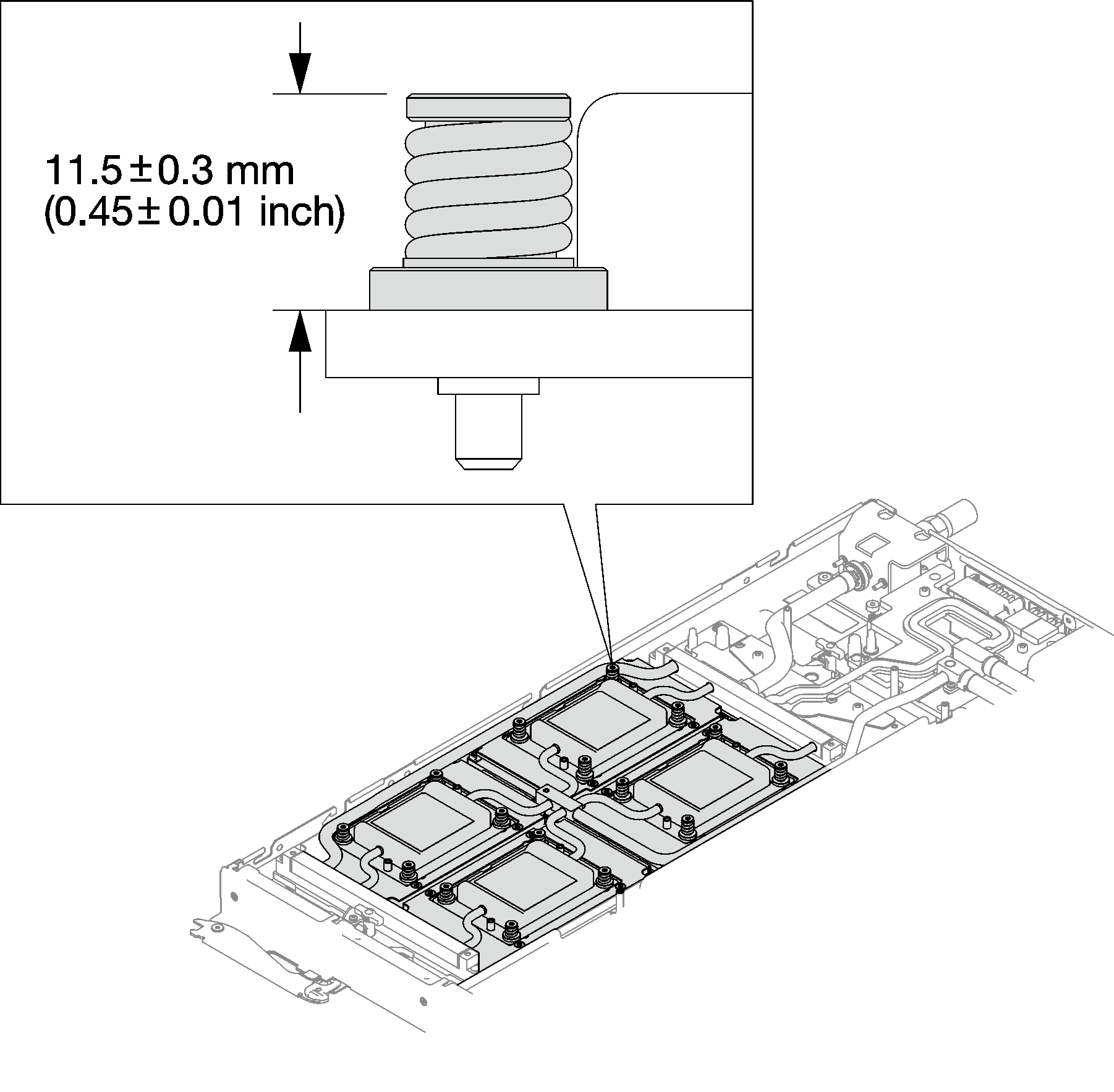
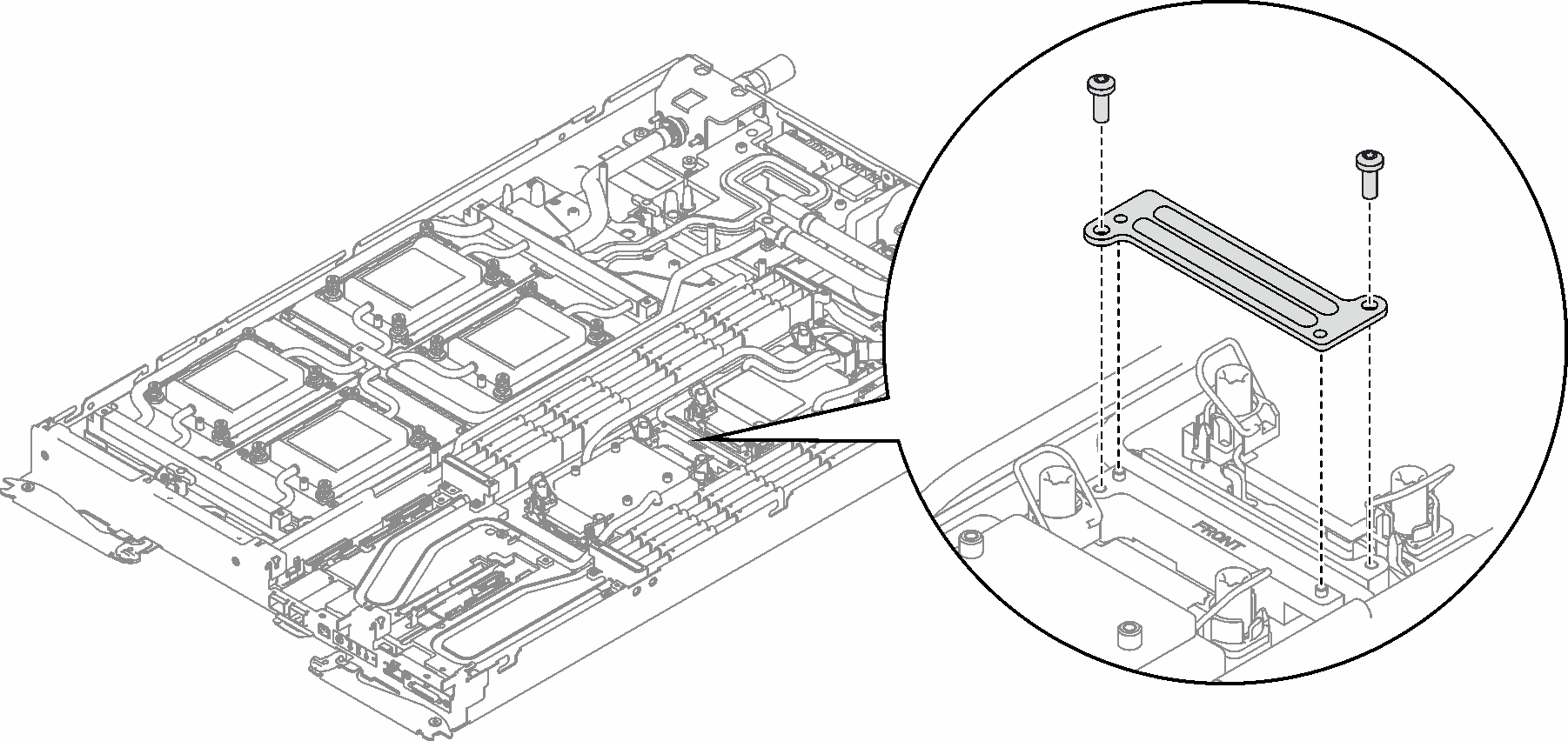
- Install VR clamp plate into the node and install two Torx T10 screws.Figure 26. VR clamp plate installation
Connect and route the cables in the tray. See GPU node cable routing.
Install the PCIe riser assembly. See Install a PCIe riser assembly (ConnectX-6) , PCIe riser assembly replacement (ConnectX-7 NDR 200), or Install a PCIe riser assembly (ConnectX-7 NDR 400).
Install the drive cage. See Install a drive cage assembly.
Install the M.2 backplane assembly. See Install the M.2 backplane assembly.
Install the memory modules. See Install a memory module.
Install the DIMM comb. See Install a DIMM comb.
Install the cross braces. See Install the cross braces.
Install the tray cover. See Install the tray cover.
Install the tray into the enclosure. See Install a DWC tray in the enclosure.
- Connect all required external cables to the solution.NoteUse extra force to connect QSFP cables to the solution.
Check the power LED on each node to make sure it changes from fast blink to slow blink to indicate all nodes are ready to be powered on.
Demo video