시스템 보드 커넥터
다음 그림은 시스템 보드의 내부 커넥터를 보여줍니다.
다음 그림은 컴퓨팅 노드의 시스템 보드에서 DIMM 슬롯 번호의 위치를 보여줍니다.
그림 1. 컴퓨팅 노드 시스템 보드의 DIMM 슬롯 번호
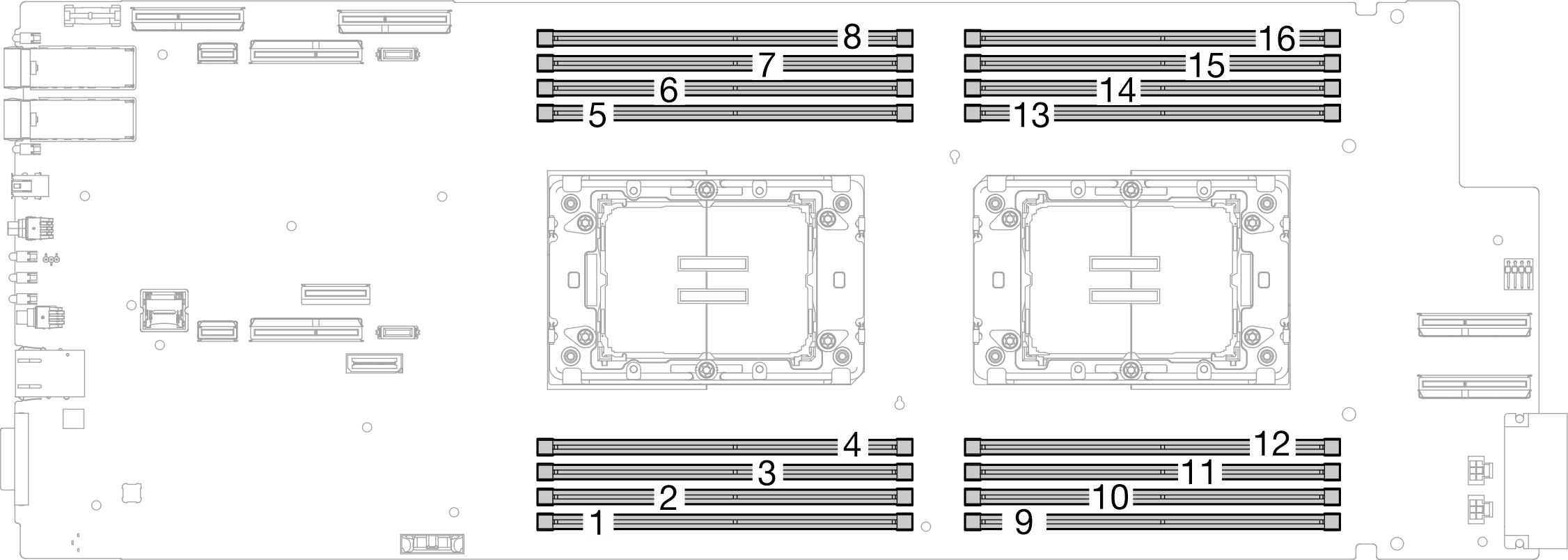
그림 2. 프로세서 위치
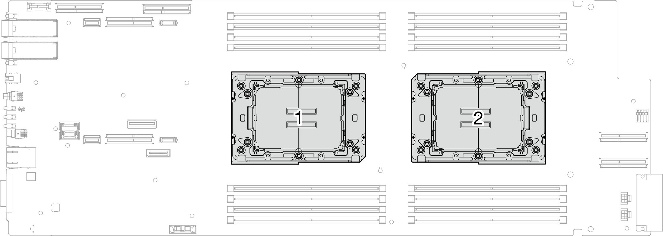
그림 3. 컴퓨팅 노드 시스템 보드의 내부 커넥터
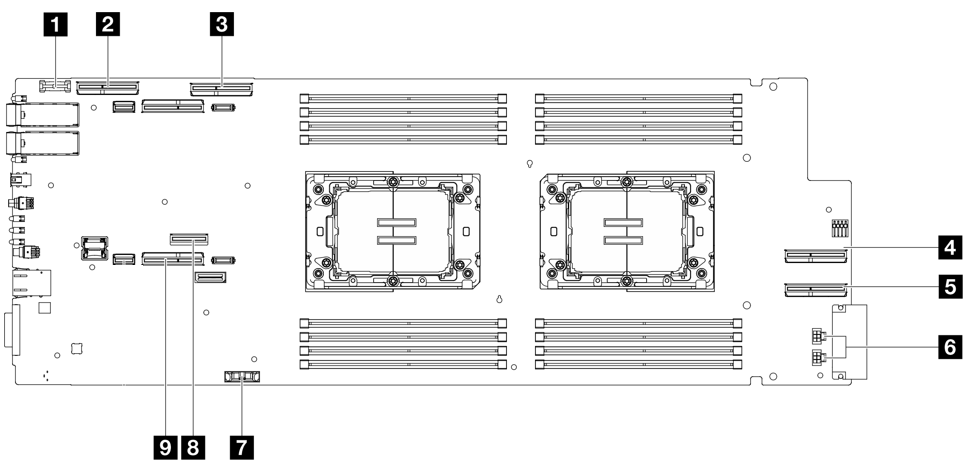
| 1 TCM(Trusted Cryptographic Module) 커넥터 | 6 드라이브 전원 커넥터 1 및 2 |
| 2 PCIe x 16 MCIO 1 커넥터 | 7 CMOS 배터리(CR2032) 커넥터 |
| 3 PCIe x 16 MCIO 2 커넥터 | 8 M.2 커넥터 |
| 4 PCIe x 16 MCIO 3 커넥터 | 9 NVMe 2-3 커넥터 |
| 5 PCIe x 16 MCIO 4 커넥터 |
피드백 보내기