System-board connectors
The following illustrations show the internal connectors on the system board.
The following illustration shows the location of the DIMM slots numbering on the system board of the compute node.
Figure 1. DIMM slots numbering on compute node system board
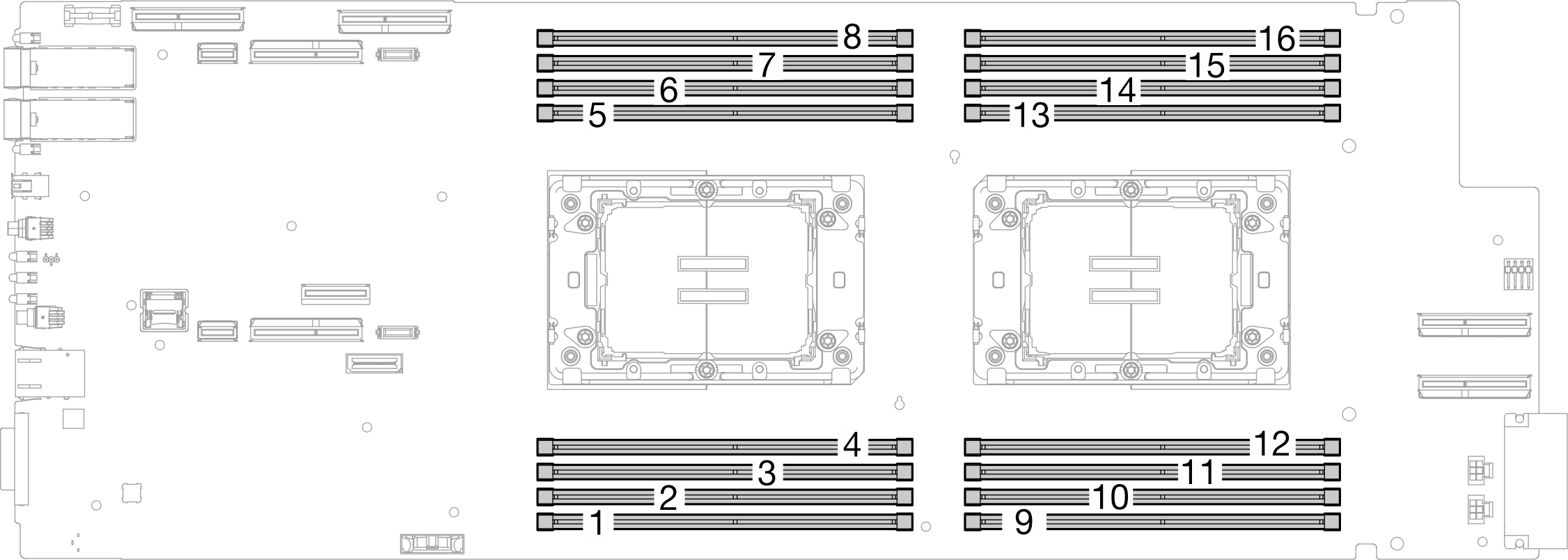
Figure 2. Processor locations
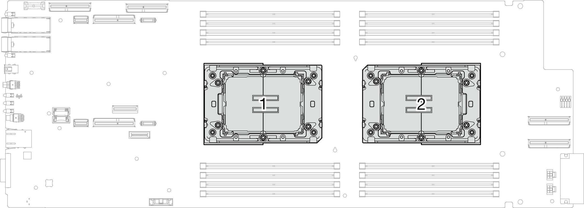
Figure 3. Internal connectors on compute node system board
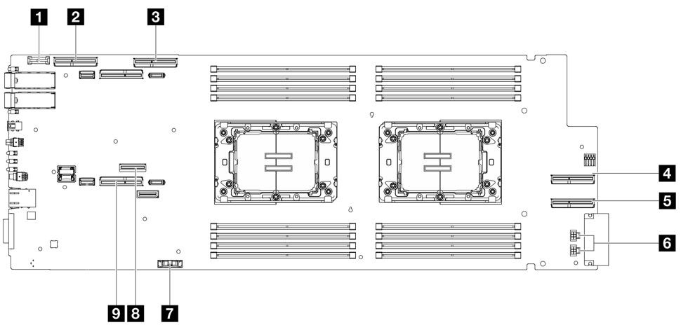
| 1 Trusted cryptographic module (TCM) connector | 6 Drive power connector 1 and 2 |
| 2 PCIe x 16 MCIO 1 connector | 7 CMOS battery (CR2032) connector |
| 3 PCIe x 16 MCIO 2 connector | 8 M.2 connector |
| 4 PCIe x 16 MCIO 3 connector | 9 NVMe 2-3 connector |
| 5 PCIe x 16 MCIO 4 connector |
Give documentation feedback