Compute node
The following illustration shows the internal connectors on the system board of the compute node.
Figure 1. Internal connectors on the system board of the compute node
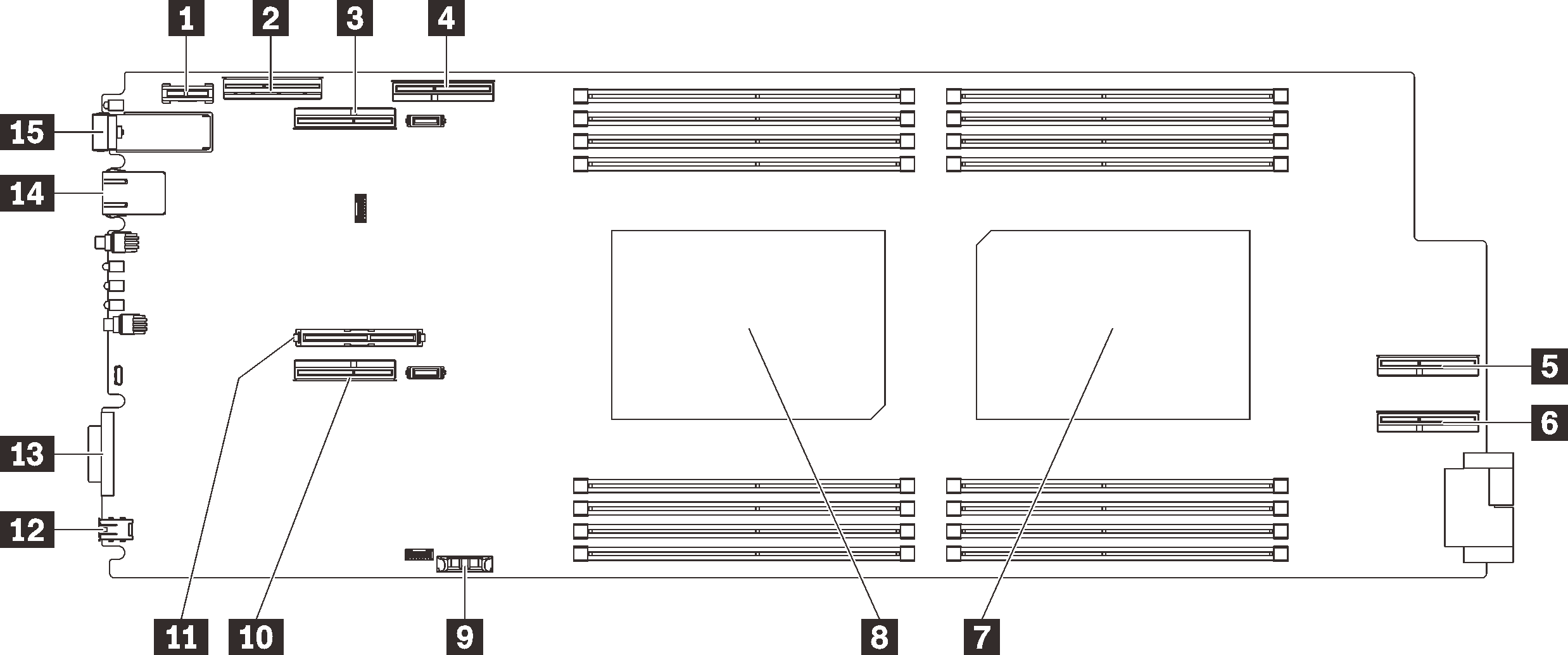
| 1 Trusted cryptographic module (TCM) connector | 9 CMOS battery (CR2032) connector |
| 2 NVMe/SATA connector | 10 PCIe 1 (riser 1) connector |
| 3 PCIe 2 (riser 2) connector (shared with GPU) | 11 M.2 connector |
| 4 PCIe 3 connector (for GPU) | 12 External LCD diagnostics handset connector |
| 5 PCIe 4 connector (for GPU) | 13 KVM connector |
| 6 PCIe 5 connector (for GPU) | 14 1 Gb Ethernet connector |
| 7 Processor 2 connector | 15 25 Gb Ethernet connector |
| 8 Processor 1 connector |
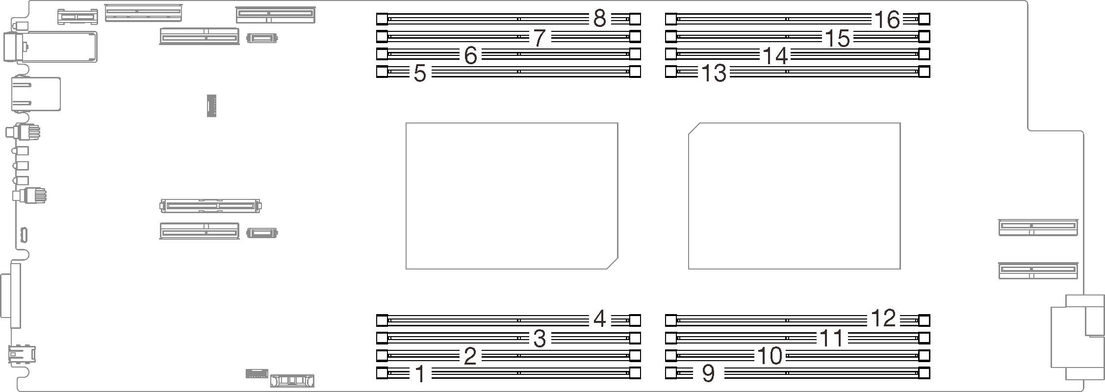
The following illustration shows the location of the DIMM connectors on the system board of the compute node.
Figure 2. The location of the DIMM connectors on the system board of the compute node
Give documentation feedback