Remove a PCIe riser assembly
Use this information to remove a PCIe riser assembly.
About this task
- Read the following sections to ensure that you work safely.
- Turn off the corresponding DWC tray that you are going to perform the task on.NoteIf Shared I/O adapters are installed, power off the auxiliary node (node 1/3/5/7/9/11) first, and then power off the primary node (node 2/4/6/8/10/12).
- Disconnect all external cables from the enclosure.NoteUse extra forces to disconnect QSFP cables if they are connected to the solution.
- Use extra forces to disconnect QSFP cables if they are connected to the solution.Figure 1. Disconnecting QSFP cables from SD650 V2 tray
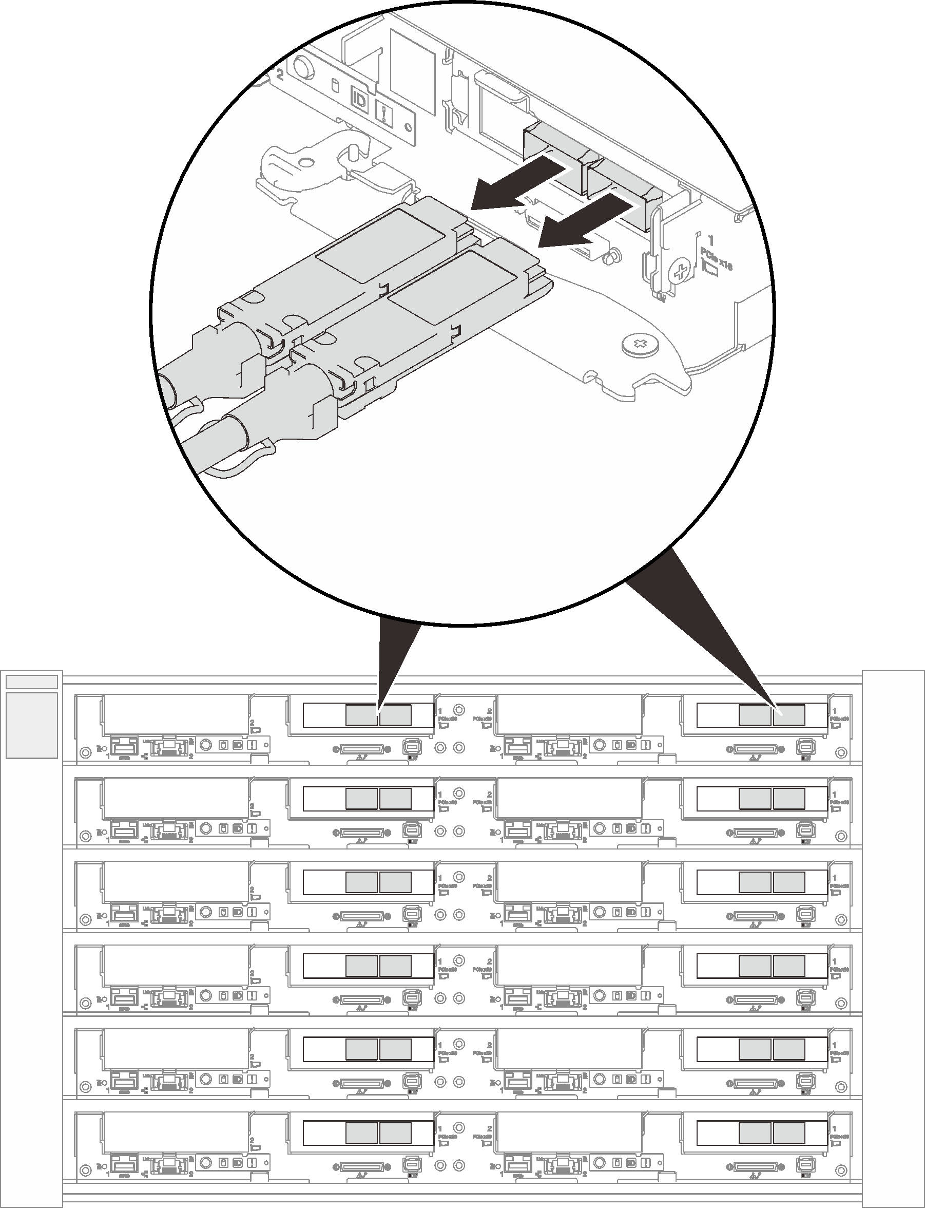 Figure 2. Disconnecting QSFP cables from SD650-N V2 tray
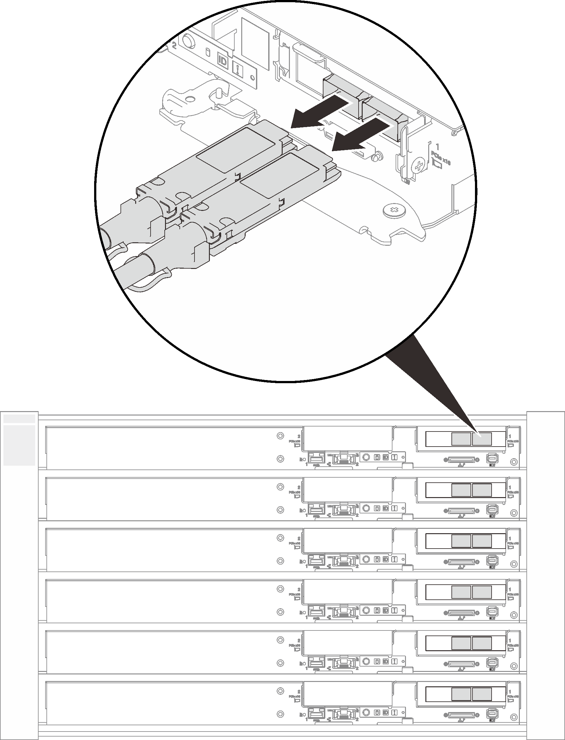
Procedure
- There are different procedures for installing the PCIe riser assembly with a general adapter or a ConnectX-6 adapter, follow the corresponding steps to complete the removal procedures.PCIe riser assembly with general adapters
Loosen the captive screw on the PCIe riser assembly.
Carefully grasp the PCIe riser-cage assembly by its edges and remove it out of the node.
Figure 3. PCIe riser assembly removal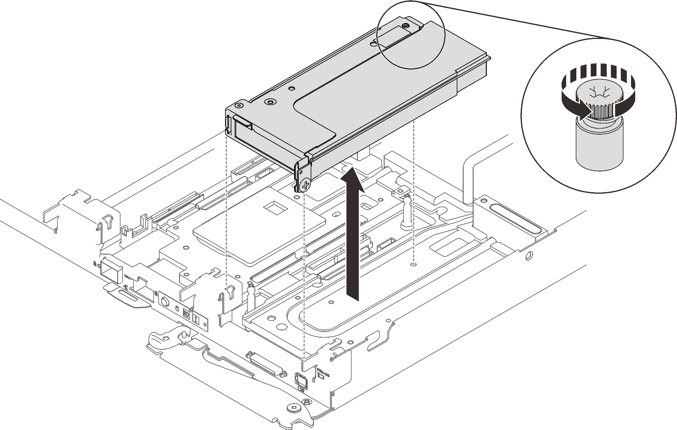
PCIe riser assembly with ConnectX-6 adapterLoosen the clamp bracket captive screw and remove it out of the node.
Figure 4. Clamp bracket captive screw removal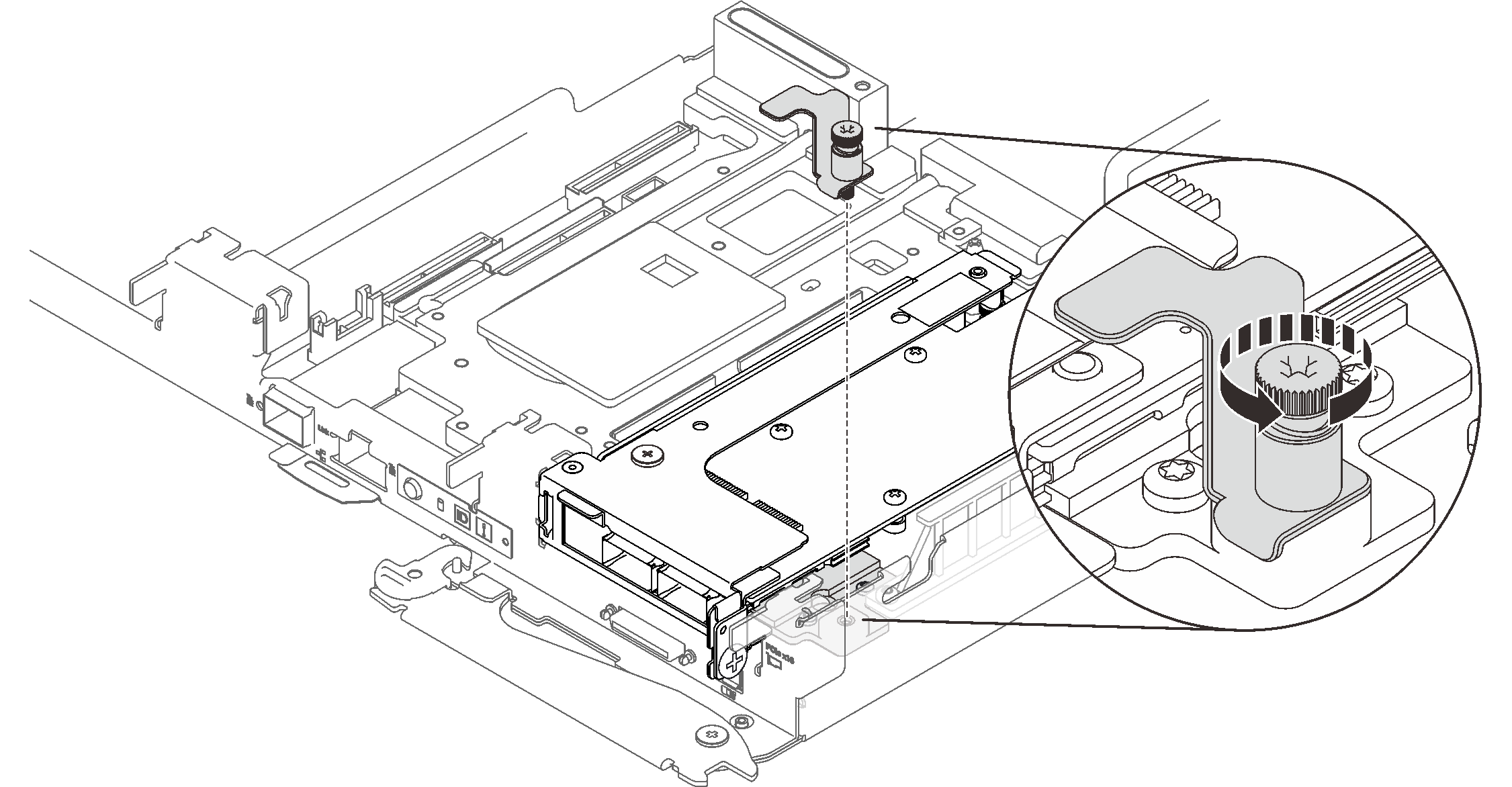
Remove the two screws; then, remove the heatpipe beam out of the node.
Figure 5. Heatpipe beam removal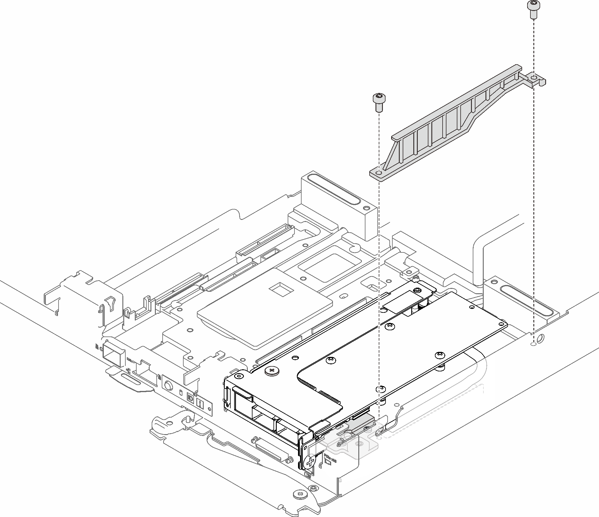
Remove the screw and loosen the captive screw on the PCIe riser assembly; then, carefully grasp the PCIe riser-cage assembly by its edges and remove it out of the node.
Figure 6. PCIe riser assembly removal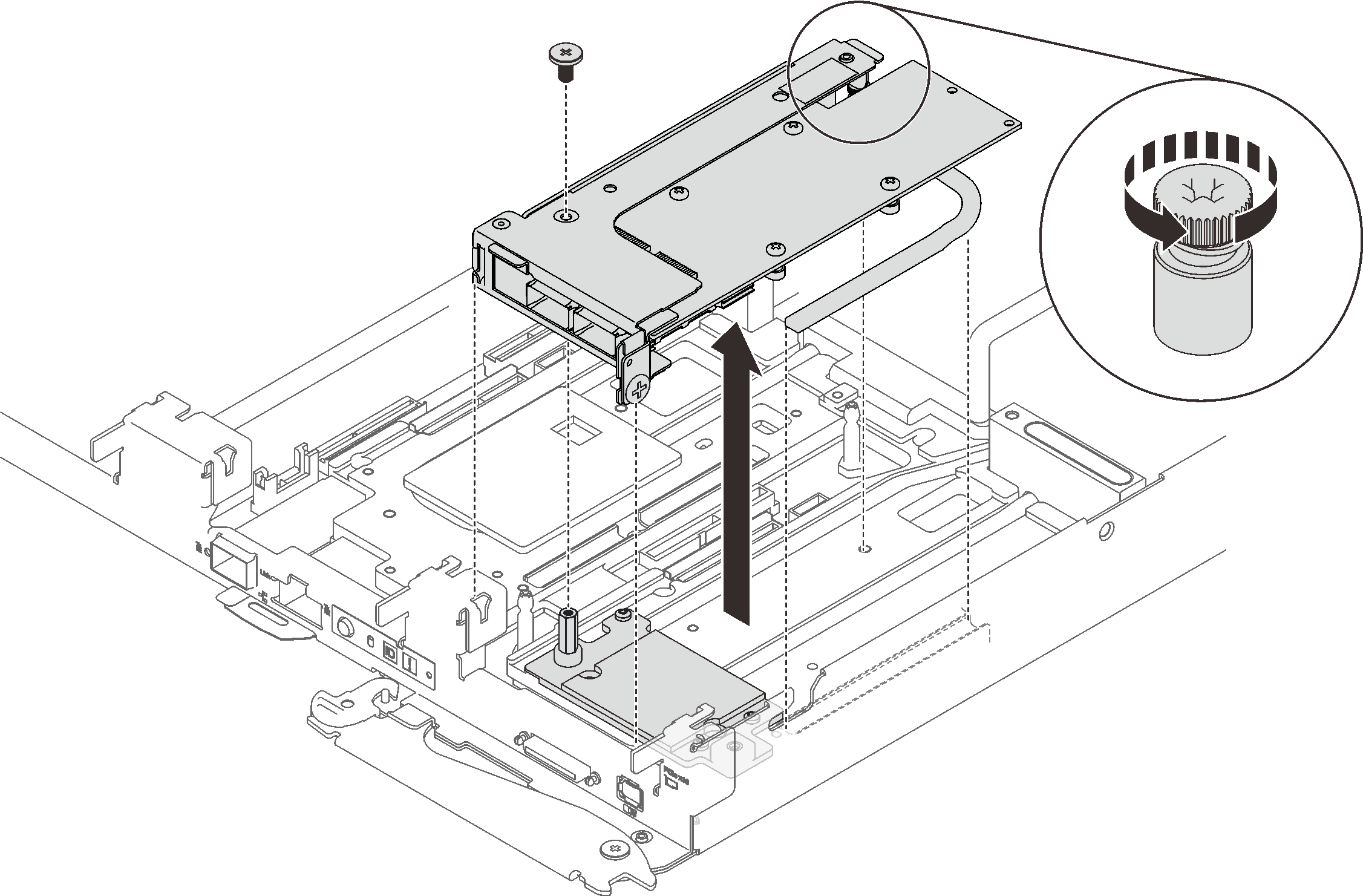
Remove the cold plate if needed.
Remove the hex screw and three Torx T10 screws.
Remove the cold plate out of the node.
Figure 7. Cold plate removal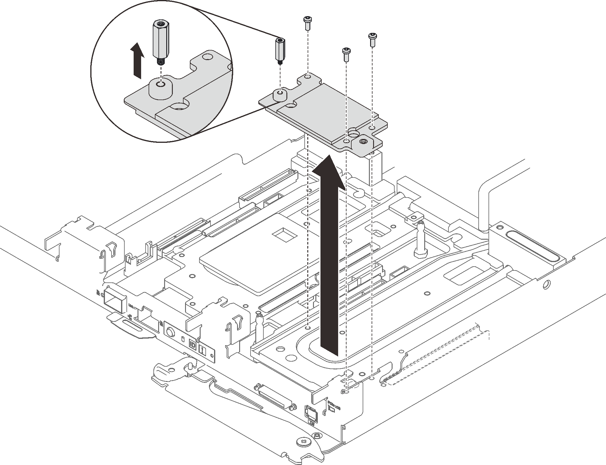
If you are instructed to return the component or optional device, follow all packaging instructions, and use any packaging materials for shipping that are supplied to you.
Remove the two screws, then, separate the expansion board from the cage.
Figure 8. Expansion board removal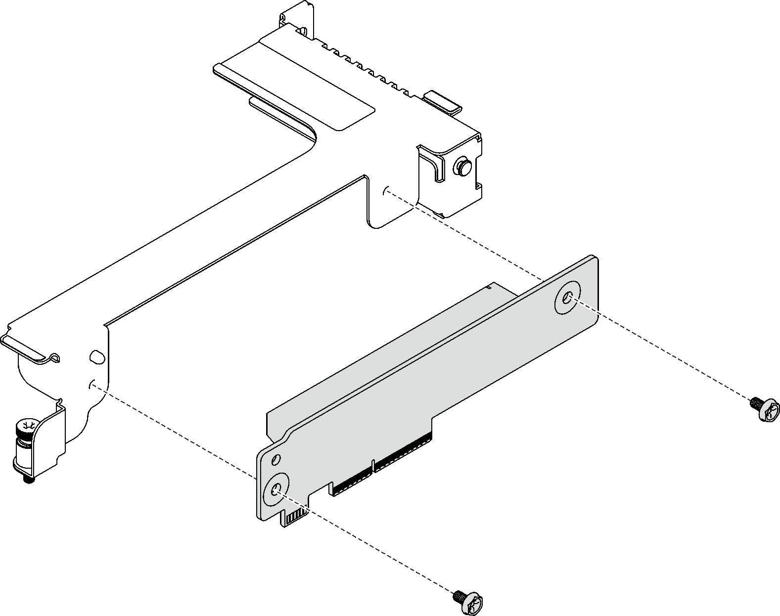
Recycle the unit in compliance with local regulations.
Demo video