Install a PCIe riser assembly
Use this information to install a PCIe riser assembly.
About this task
Required tools
Ensure you have “SD650 V2 or SD650-N V2 Neptune® DWC Waterloop Service Kit “ in hand to install components.
Before replacing the gap pad/putty pad, gently clean the interface plate or the hardware surface with an alcohol cleaning pad.
Hold the gap pad/putty pad carefully to avoid deformation. Make sure no screw hole or opening is blocked by the gap pad/putty pad material.
Do not use expired putty pad. Check the expiry date on putty pad package. If the putty pads are expired, acquire new ones to properly replace them.
- Read the following sections to ensure that you work safely.
See Internal cable routing for cable routing details.
- For PCIe riser with regular adapter, see Install a PCIe riser assembly with regular adapter.
- For PCIe riser with ConnectX-6 adapter, see Install a PCIe riser assembly with ConnectX-6 adapter.
Install a PCIe riser assembly with regular adapter
Procedure
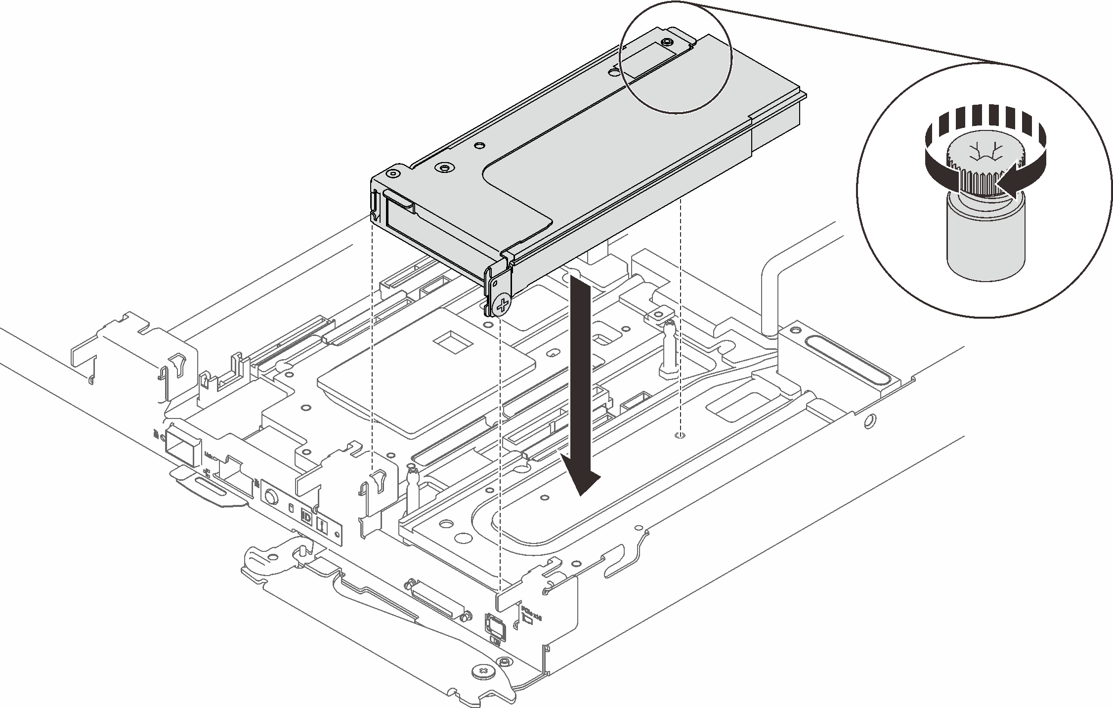
- Fasten the captive screw on the PCIe riser assembly.Figure 1. PCIe riser assembly installation
Install a PCIe riser assembly with ConnectX-6 adapter
Procedure
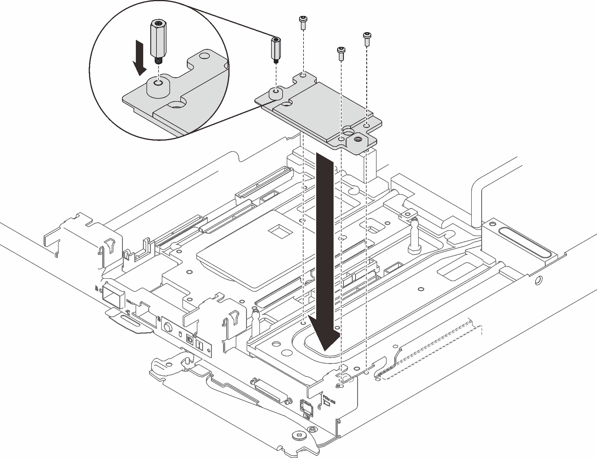
- Place the cold plate on the node; then, secure the cold plate with one hex standoff screw and three Torx T10 screws.Figure 2. Cold plate installation
- Replace the cold plate putty gap pad with a new one.Figure 3. Cold plate putty pad for CX-6 riser
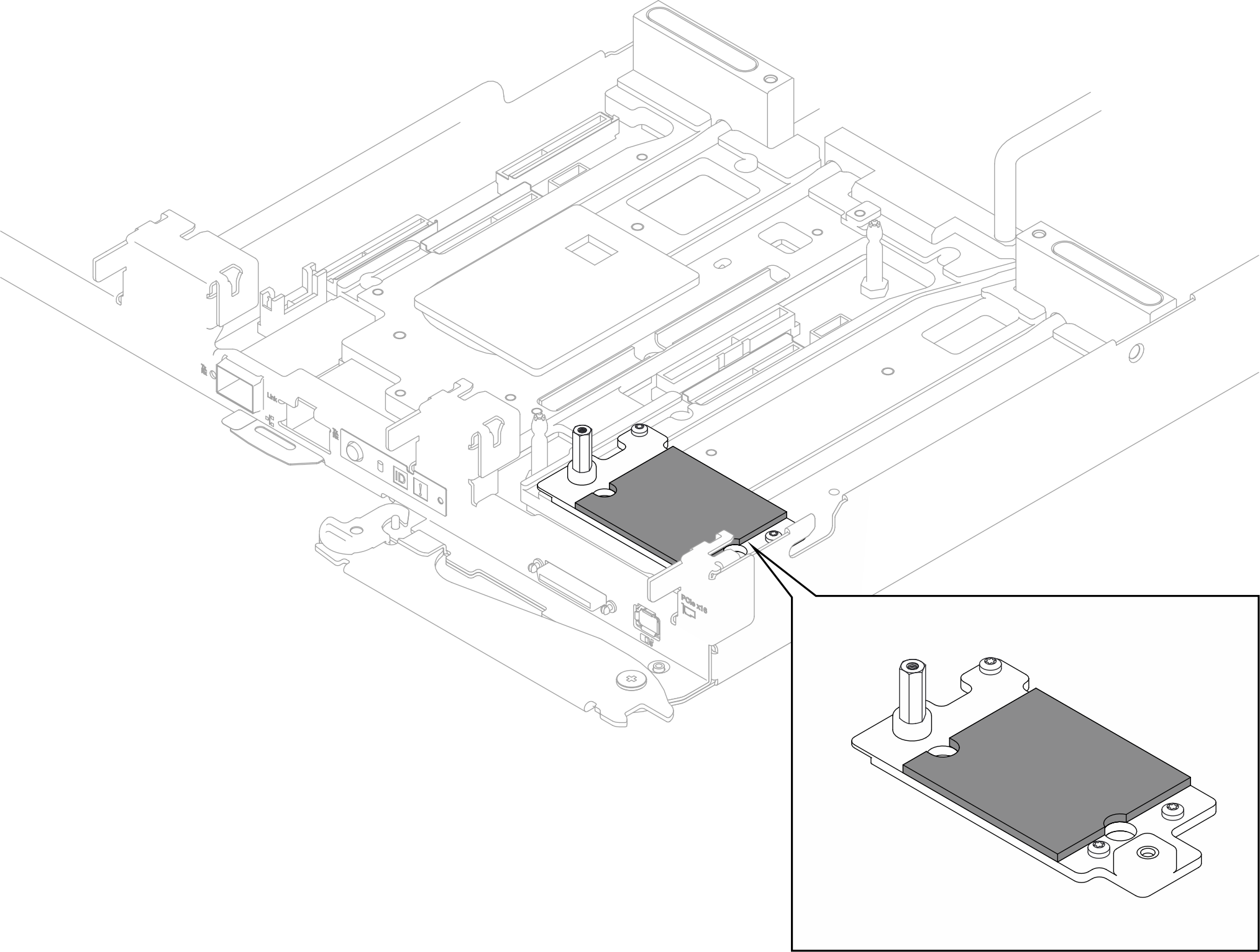
Make sure to follow Gap pad/putty pad replacement guidelines.
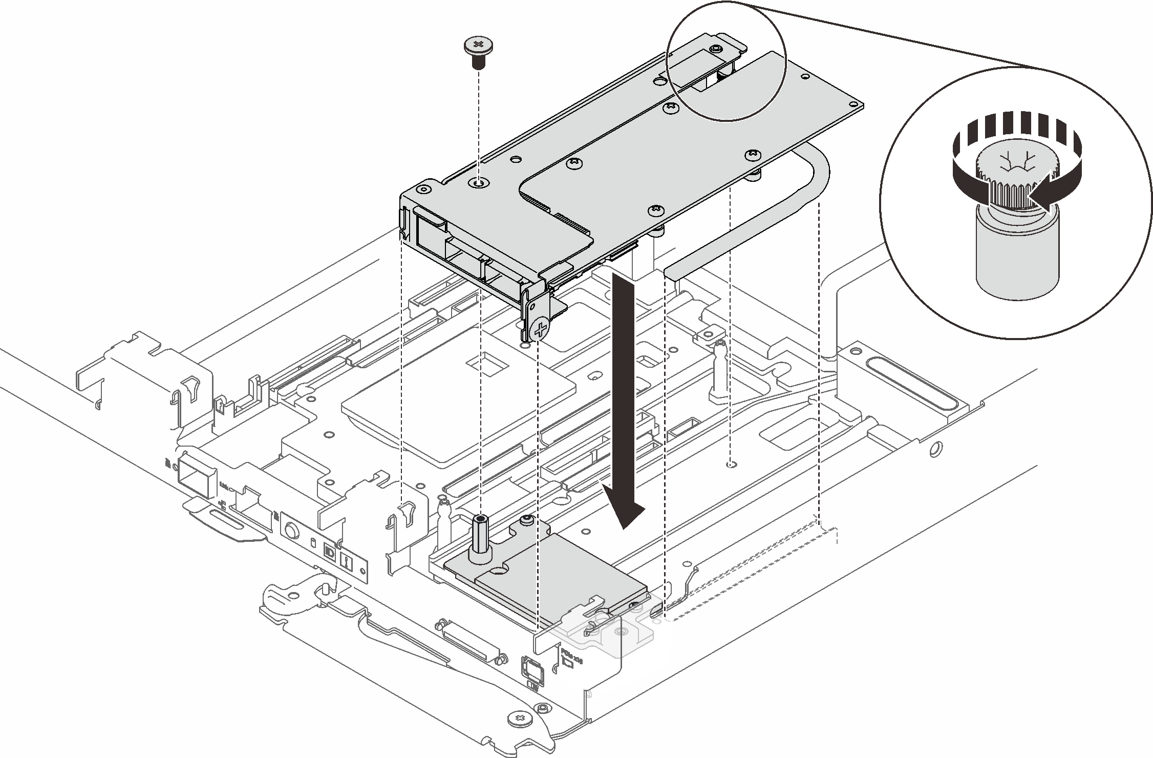
- Align the two tabs on the PCIe riser assembly with the slots on the front node; then, insert the PCIe riser assembly onto the system board; then, secure the riser assembly with a screw, and fasten the captive screw.Figure 4. PCIe riser assembly installation
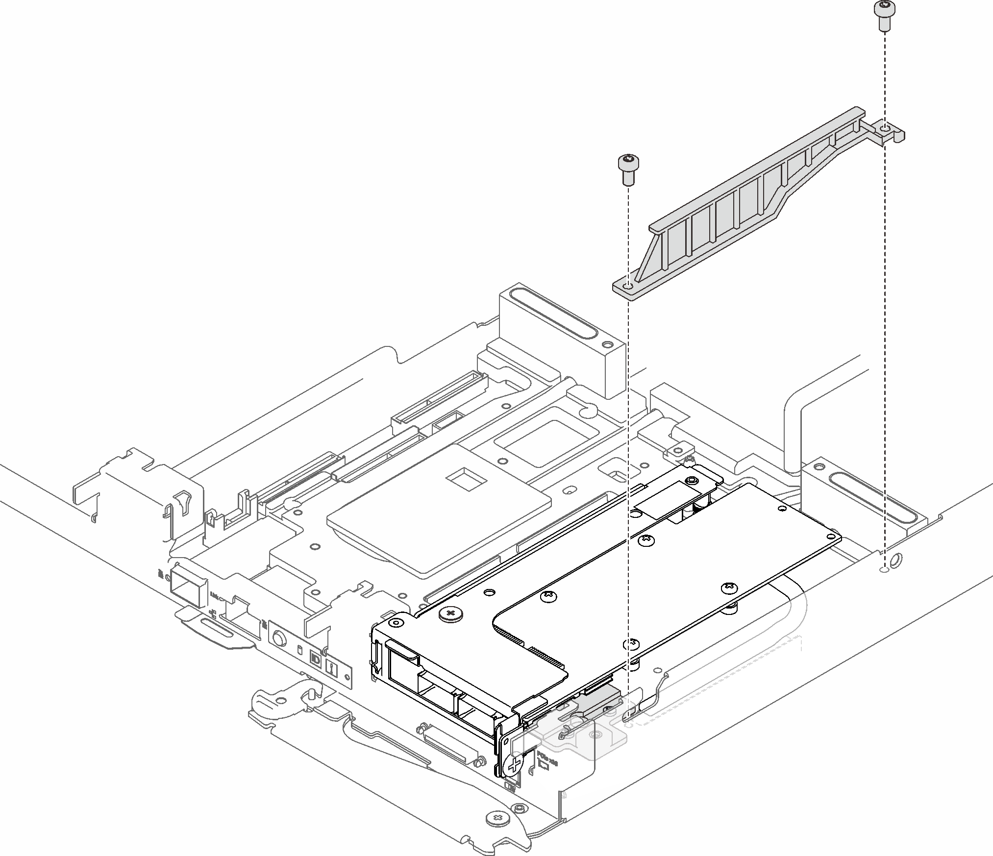
- Install the heatpipe beam, and secure it with two screws.Figure 5. Heatpipe beam installation
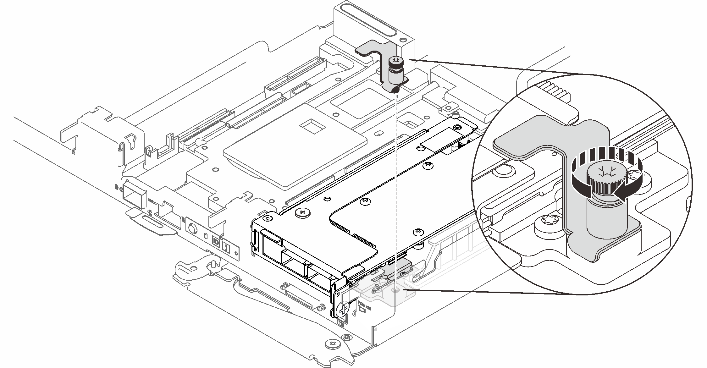
- Install the clamp bracket captive screw and fasten it.Figure 6. Clamp bracket captive screw installation
- Proceed to the next step based the type of ConnectX-6 adapter that is installed in the riser:
Stand-alone ConnectX-6 adapter:
Skip to After you finish.
Shared I/O
Refer to the following table to see supported configurations for shared I/O ConnectX-6 adapters:
Route the cable as in the corresponding figure.
Shared I/O A (with NVMe/SATA drives and M.2 backplane):
Figure 7. Cable routing - Shared I/O A (with NVMe/SATA drives and M.2 backplane)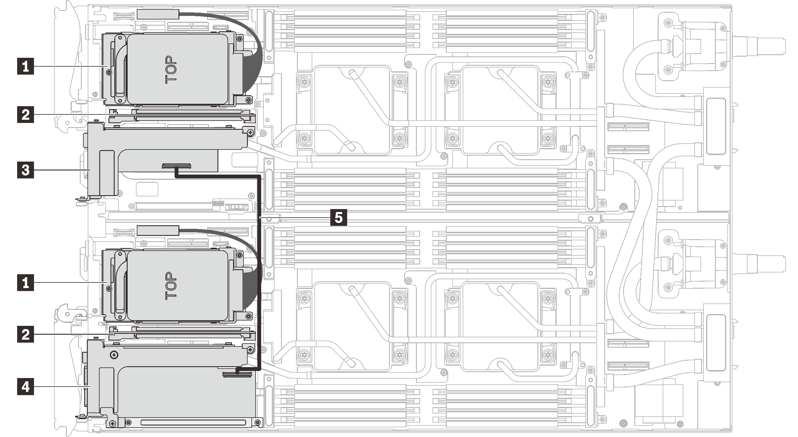
1 NVMe/SATA drives 4 Main adapter 2 M.2 backplane 5 350mm IPEX cable 3 Auxiliary adapter Shared I/O B (with M.2 backplane):
Route the cable as in the following figure.
Figure 8. Cable routing - Share I/O B (with M.2 backplane)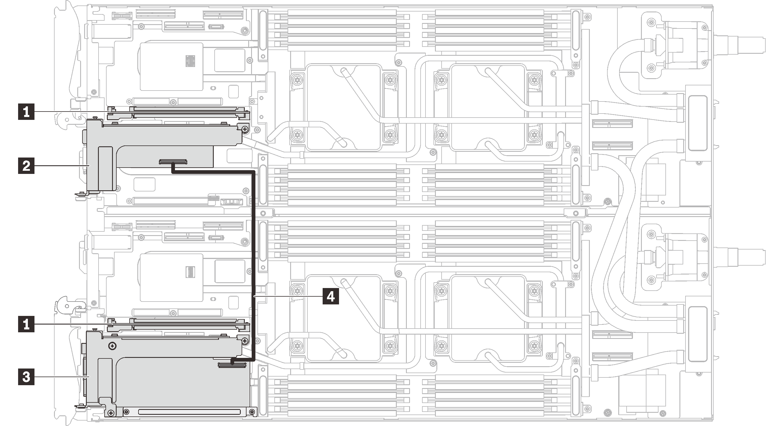
1 M.2 backplane 3 Main adapter 2 Auxiliary adapter 4 350mm IPEX cable
Reinstall the tray cover (see Install the tray cover).
Reinstall the tray (see Install a DWC tray in the enclosure).
NoteFor safety, use the lift tool to install the tray into the rack.Connect all required external cables to the enclosure.
NoteApply extra forces to connect QSFP cables to the enclosure if Mellanox ConnectX-6 adapters are installed.Figure 9. Connecting QSFP cables to SD650 V2 tray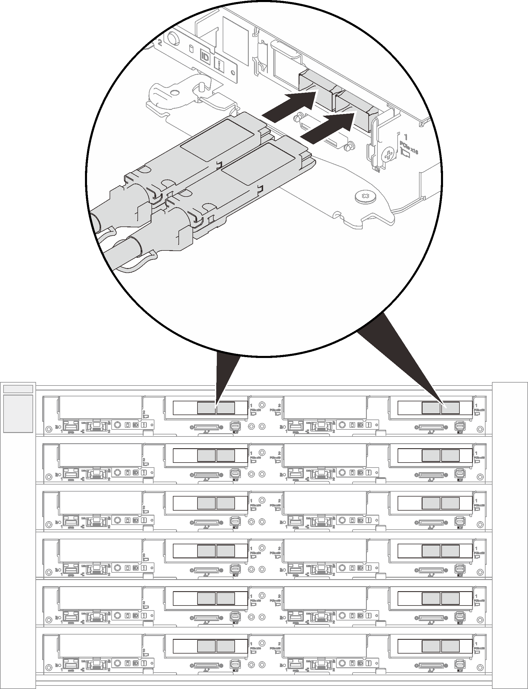 Figure 10. Connecting QSFP cables to SD650-N V2 tray
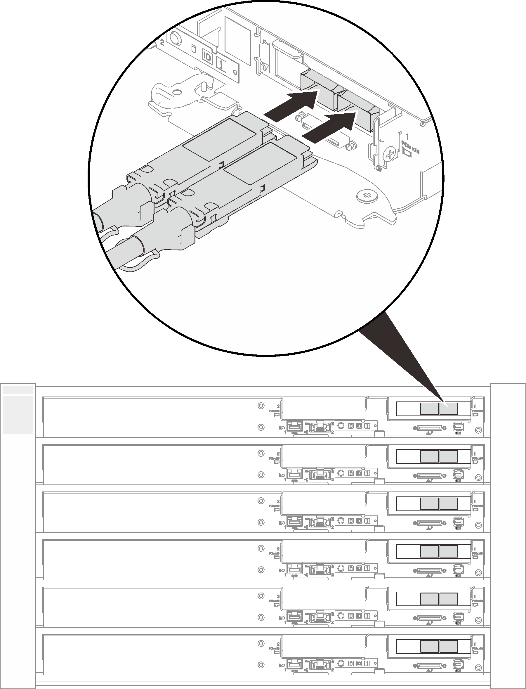
- If the installed adapters are shared I/O ones, power on the primary node (node 2/4/6/8/10/12) first; then, power on the auxiliary node (node 1/3/5/7/9/11).ImportantThe primary adapter is always installed to the right node (node 2/4/6/8/10/12), while the auxiliary adapter is installed to the left node (node 1/3/5/7/9/11). As an auxiliary node requires a connected and functioning primary node to function, always follow the following power on/off sequence:
- When powering off the nodes, always power off node 1/3/5/7/9/11 (auxiliary node) first.
- When power on the nodes, always power on 2/4/6/8/10/12 (primary node) first.
Check the power LED on each node to make sure it changes from fast blink to slow blink to indicate all nodes are ready to be powered on.
Demo video