Install the enclosure in a rack
Use this information to install the enclosure in a rack.
S002
CAUTION
The power-control button on the device and the power switch on the power supply do not turn off the electrical current supplied to the device. The device also might have more than one power cord. To remove all electrical current from the device, ensure that all power cords are disconnected from the power source.
Before you install the enclosure:
Read the Installation Guidelines to ensure that you work safely.
- Three trained technicians are needed to complete the enclosure installation/removal task.
Two technicians hold front and rear handles at both sides of the enclosure.
One technician protects cables from damage.
- To install the rails into a rack, follow the instructions that are provided in the Rail installation Guide.
- Ensure four handles are attached to the enclosure when moving the enclosure.NoteMake sure all handle posts are secured before lifting.Figure 1. Attaching four handles
Complete the following steps to install the enclosure.
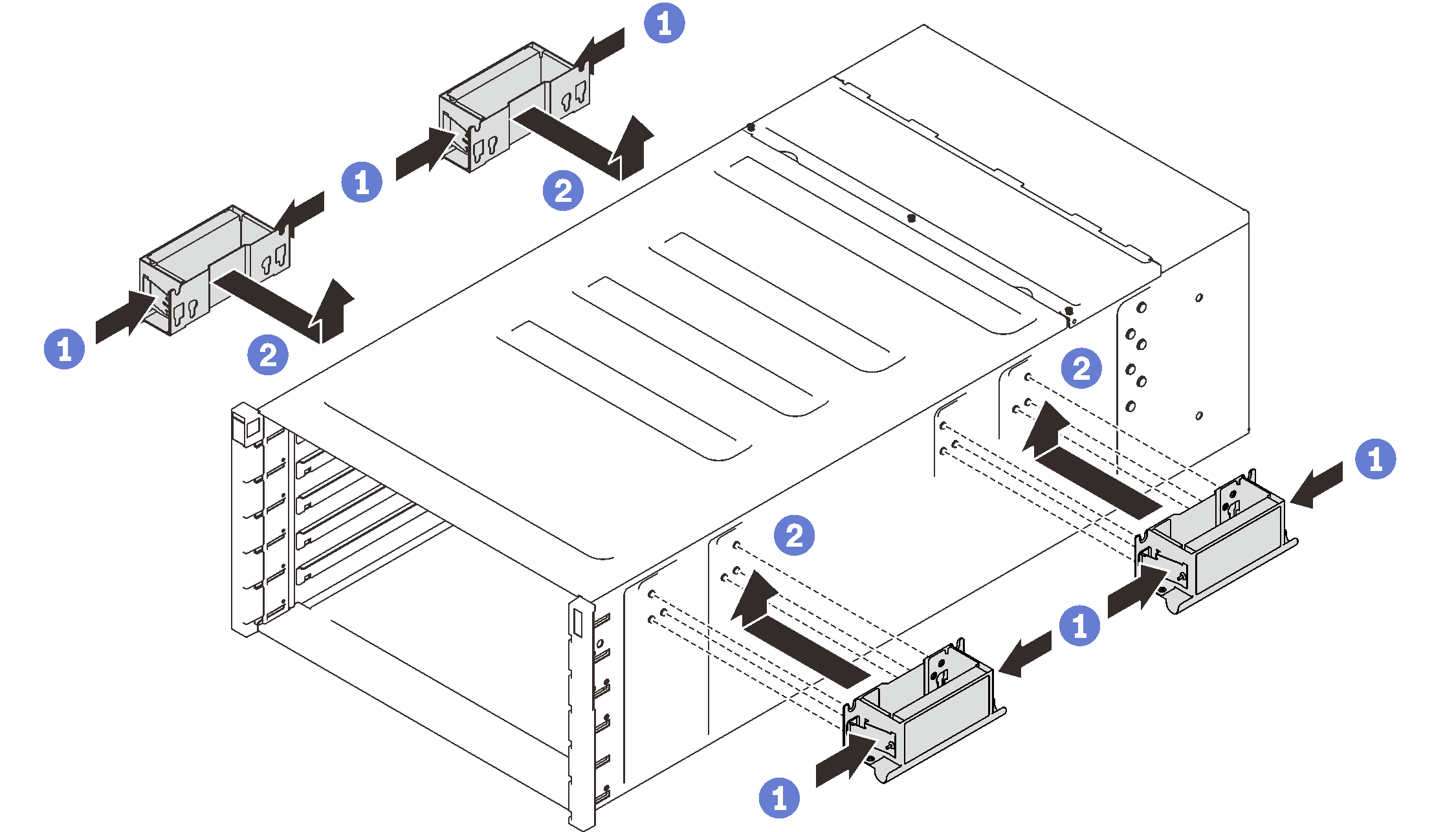
- Carefully put the enclosure into the rack and slide the enclosure until rear handles are near front rack rails; then, remove rear handles at both sides.Figure 2. Rear handle removal
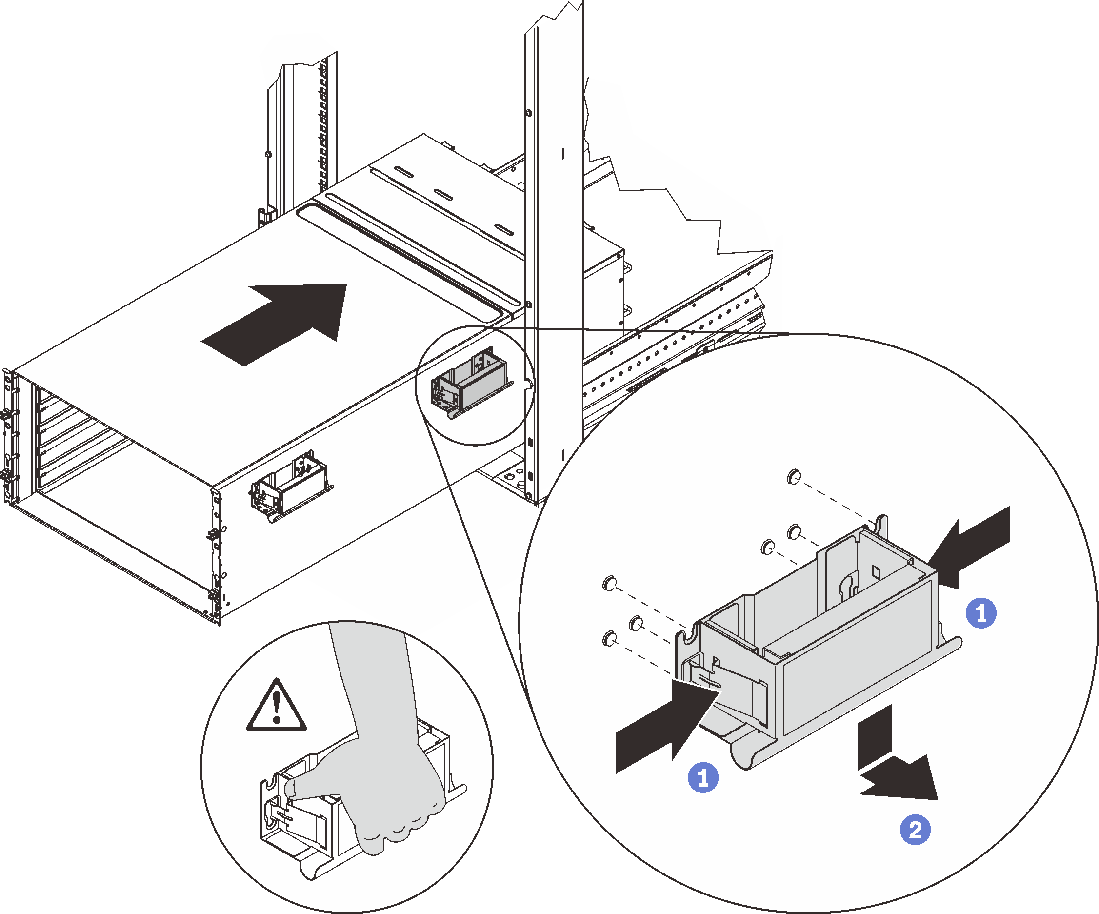
- Slide the enclosure farther into the rack until front handles are near front rack rails; then, remove front handles at both sides.Figure 3. Front handle removal
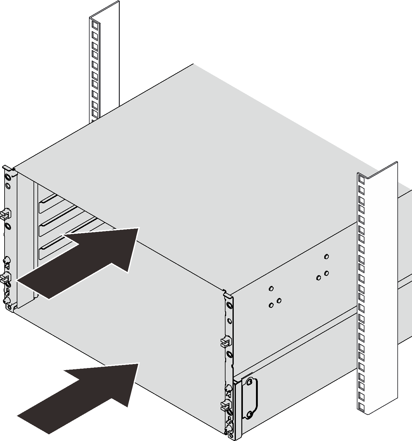
- Side the enclosure all the way back to the rack.Figure 4. Sliding the rack
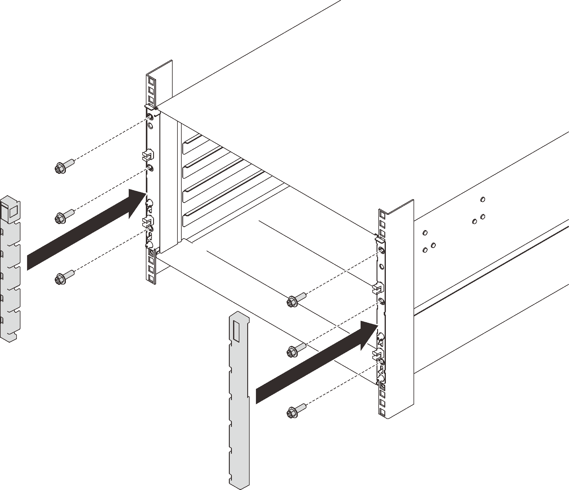
- Reinstall two EIA covers at the front of the enclosure; then, reinstall six screws.Figure 5. EIA cover installation
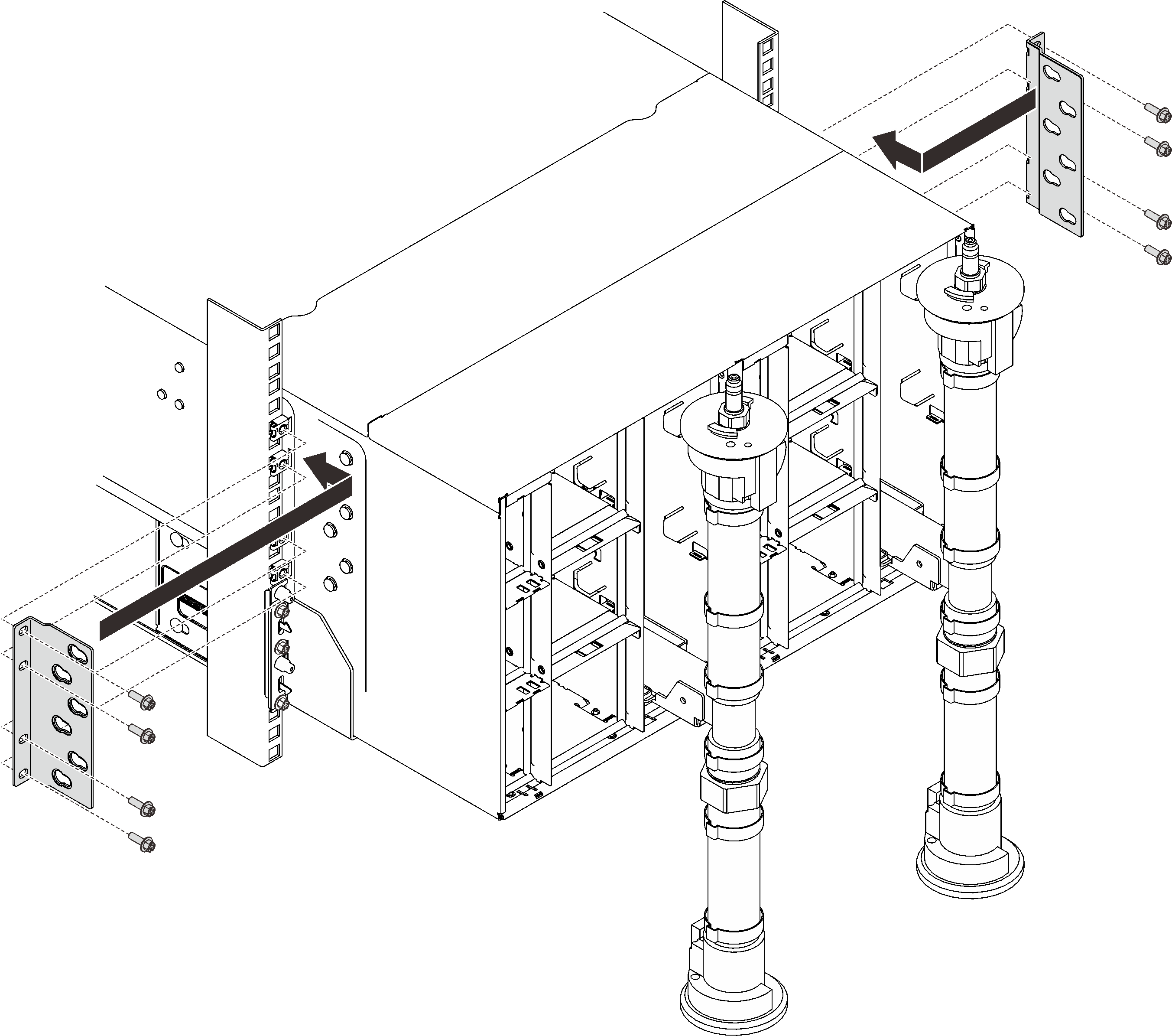
- Reinstall eight screws to secure two support brackets on the rear enclosure.Figure 6. Support bracket installation
Reassemble the enclosure and program the vital product data (VPD) that is stored on the card. Complete the following steps:
Reinstall eight screws (using the screwdriver contained in the manifold repair kit) to secure two manifolds.
Figure 7. Manifold screw locations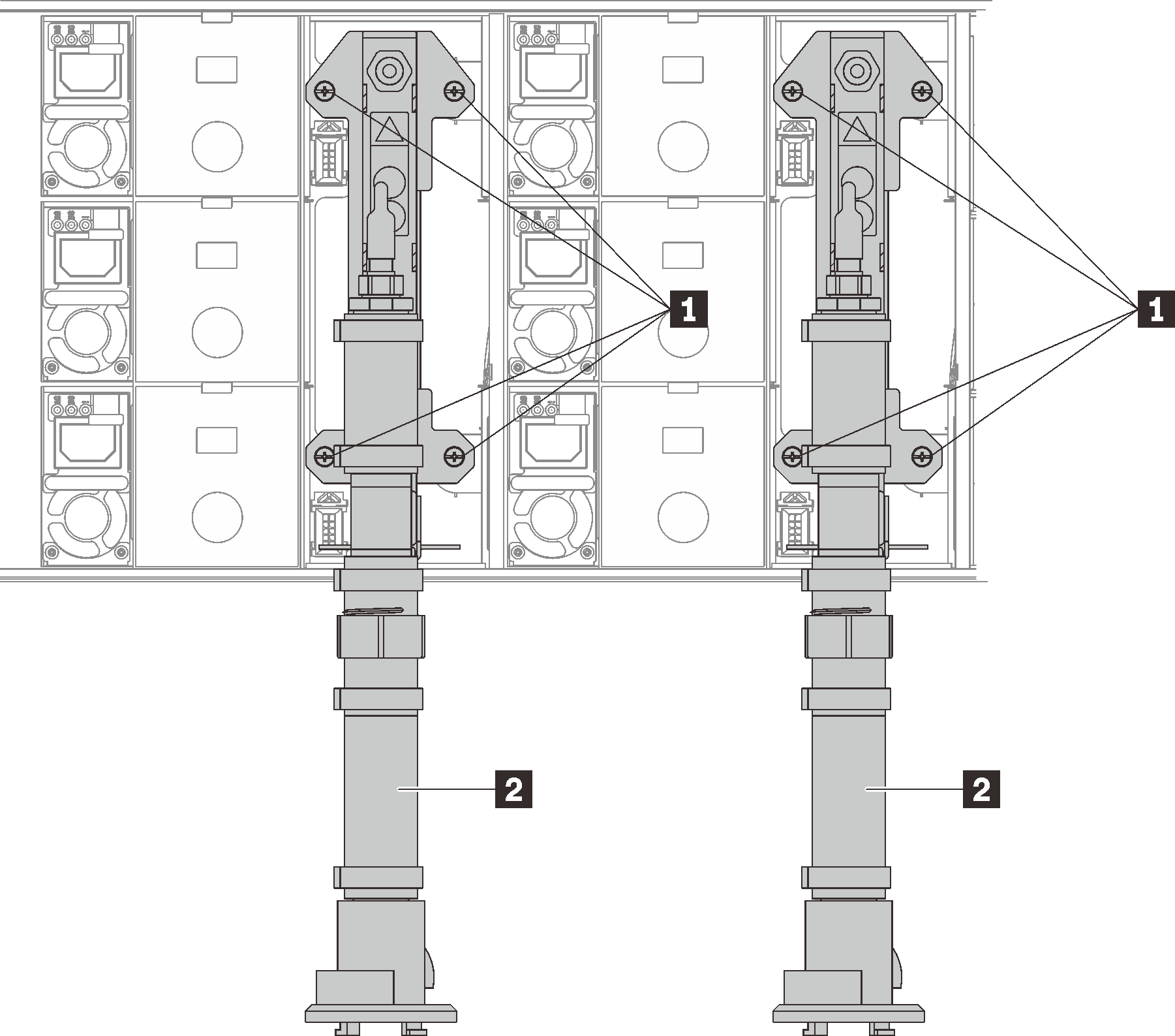
Table 1. Manifold screw locations 1 Screws 2 Manifold Reinstall all power supplies back to the enclosure.
Figure 8. Power supply installation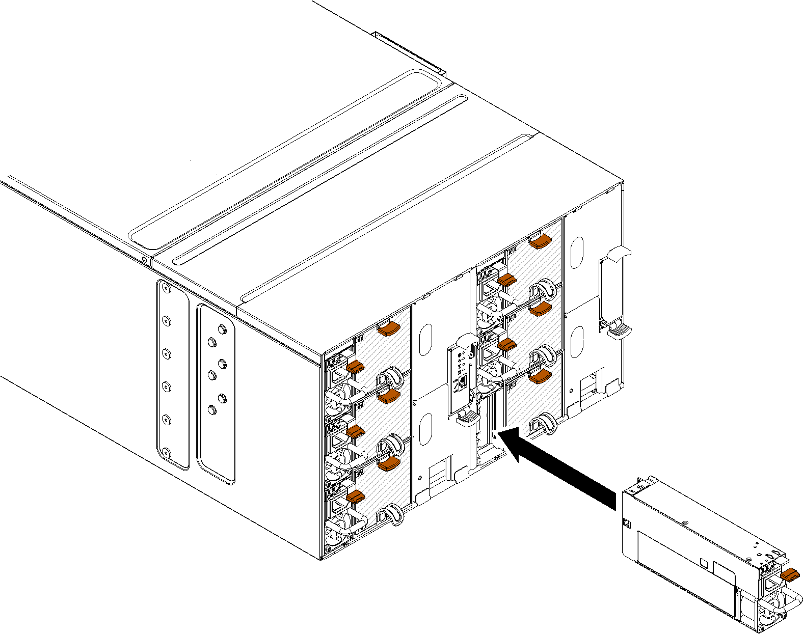
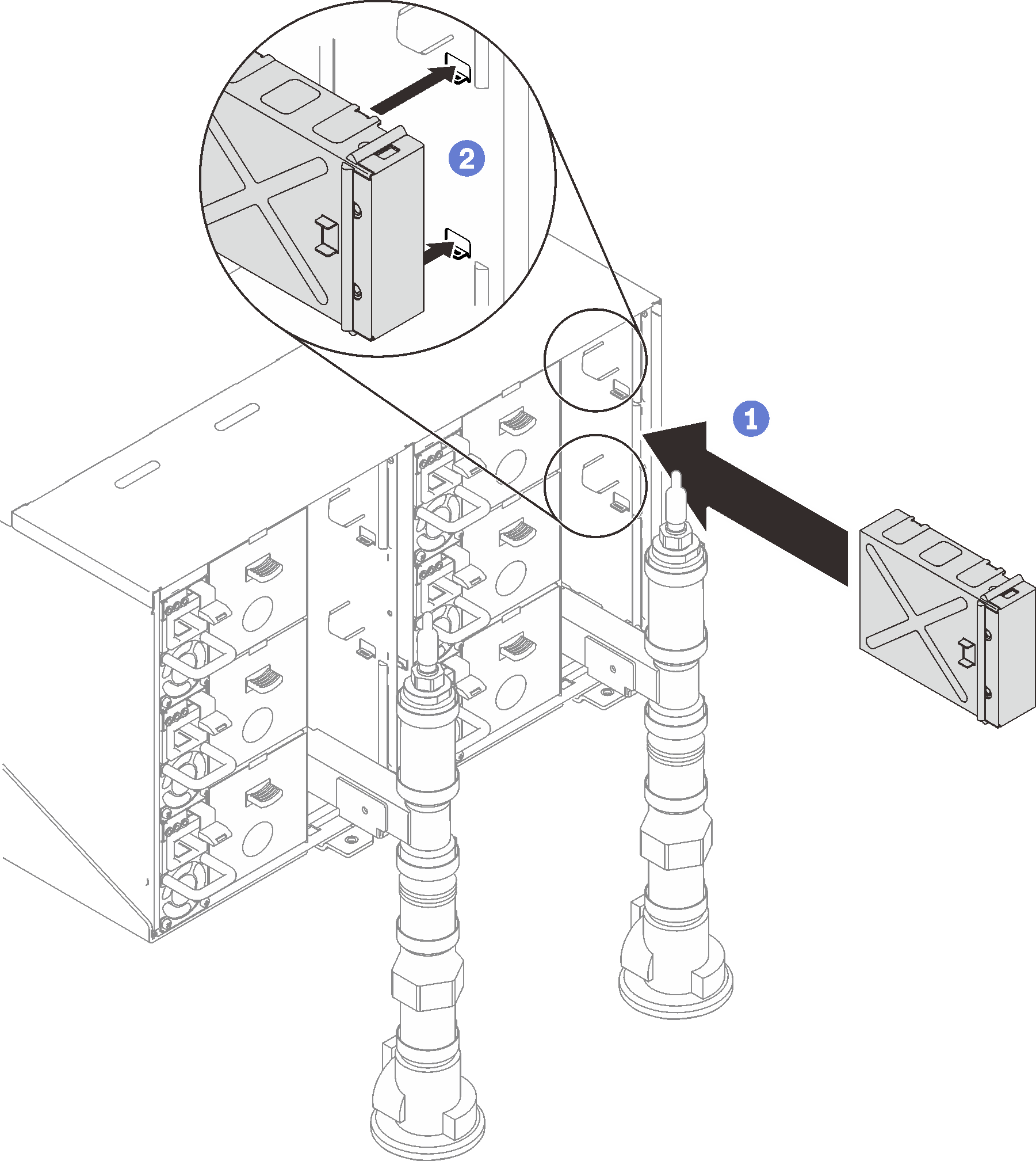
- Reinstall the blank filler.Figure 9. Blank filler installation
Reinstall FPC card module support bracket and FPC card module.
Figure 10. Support bracket installation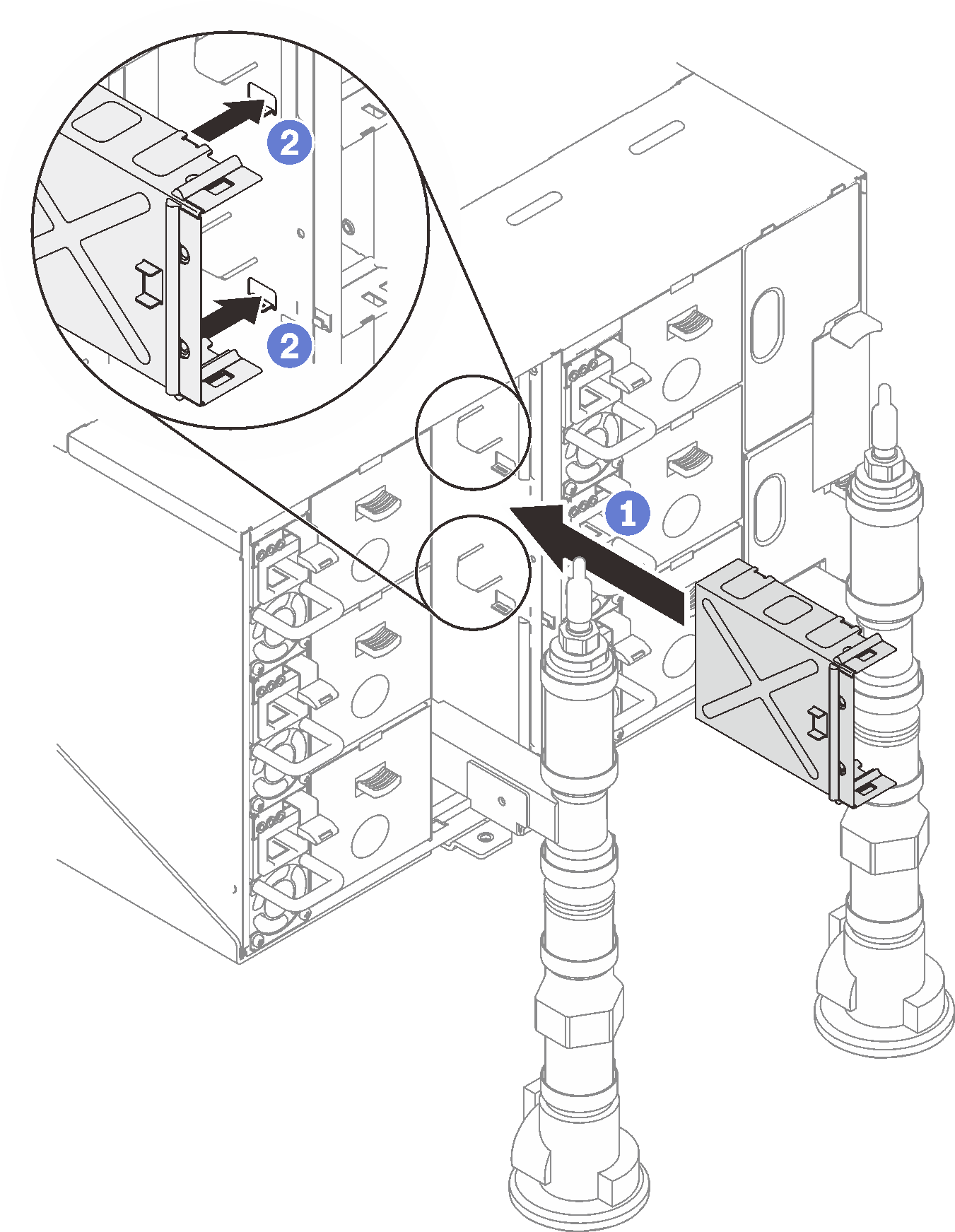 Figure 11. FPC card module installation
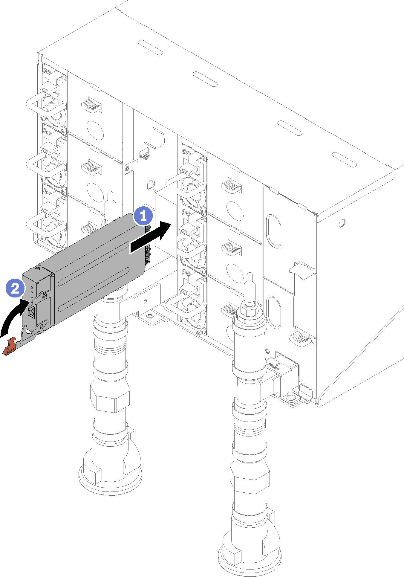
Reinstall manifold retention brackets that are retaining the manifolds (top enclosure position only).
Figure 12. Retention bracket installation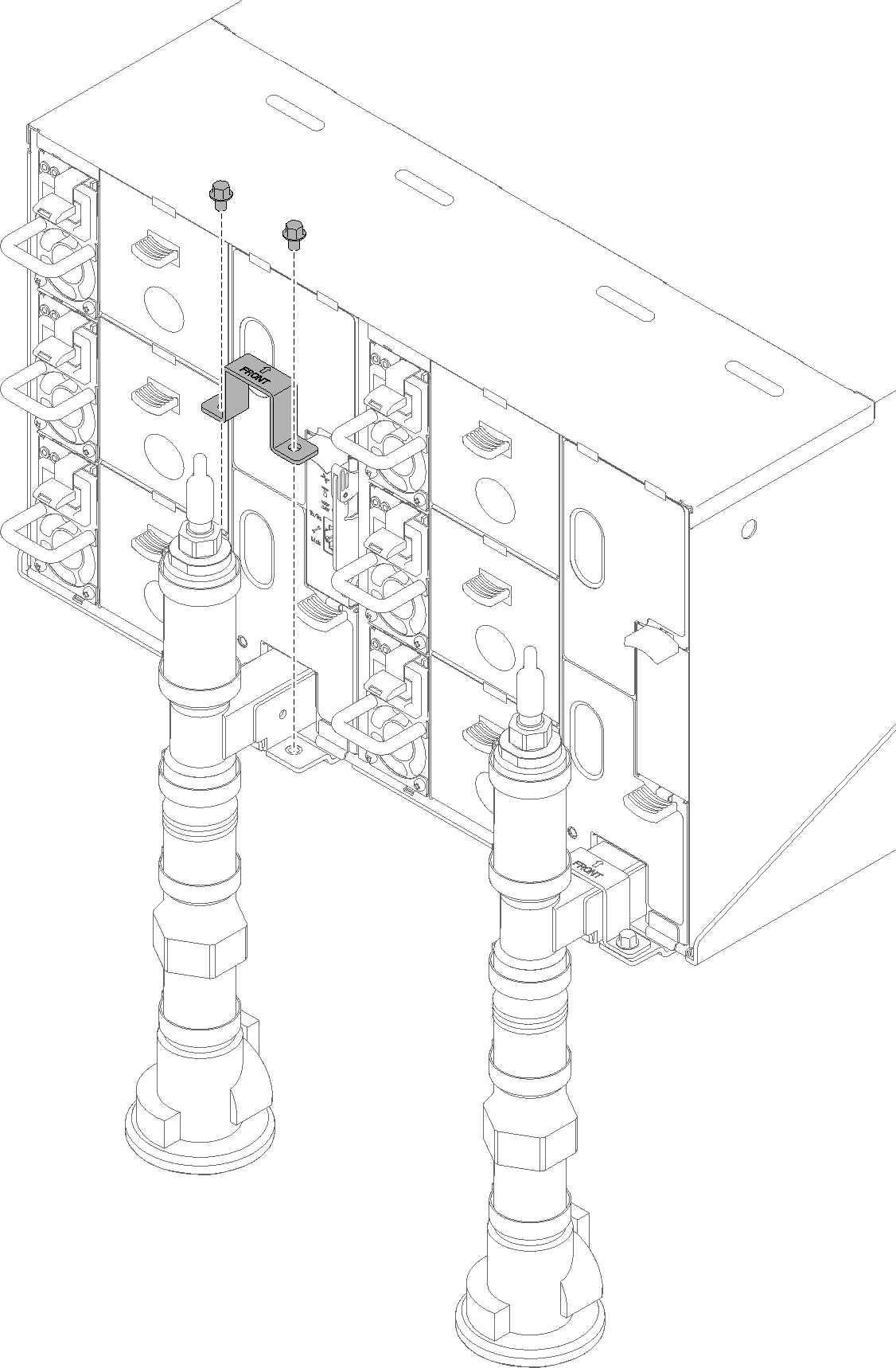
Align the drip sensor assembly with the enclosure and slide it into place.
Figure 13. Drip sensor assembly installation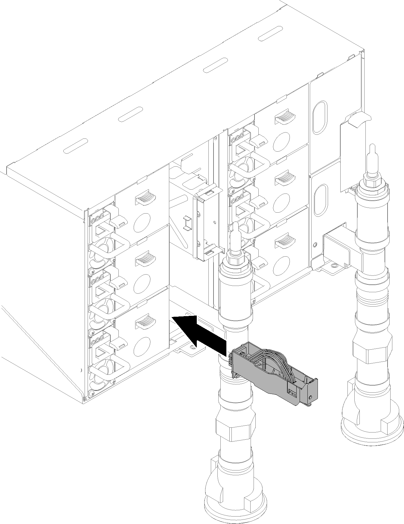
Reinstall all EMC shields.
Figure 14. Upper EMC shields installation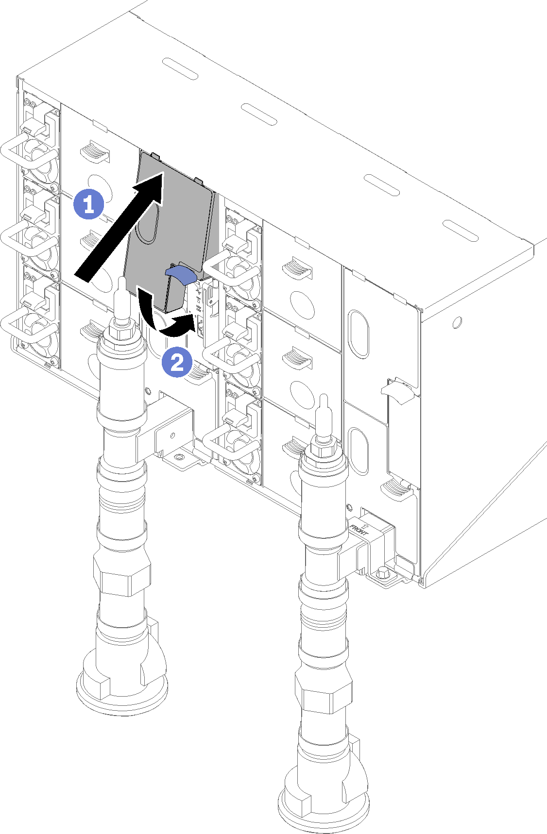 Figure 15. Lower EMC shield installation
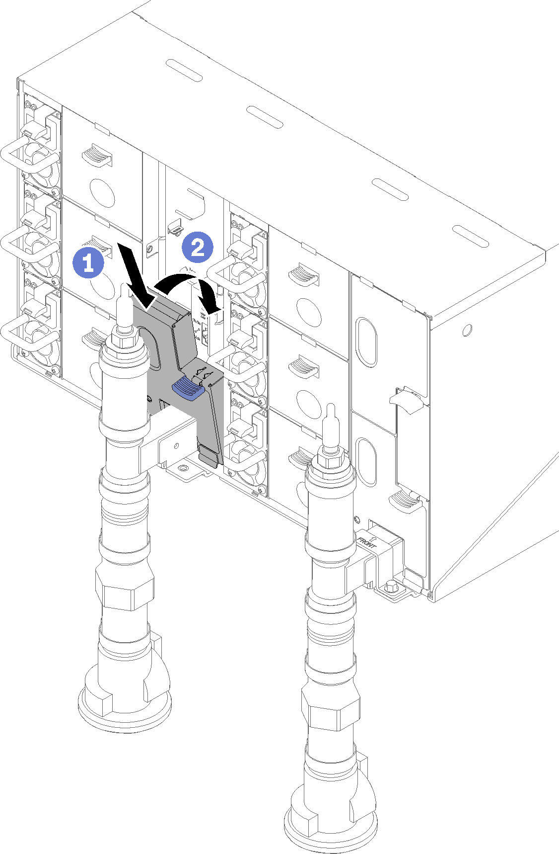
- Connect any cables that you disconnected from the modules in the rear of the enclosure.
- Connect the enclosure to power (see n1200 Enclosure Installation and Service Guide).
- Update the solution firmware to the latest level (see n1200 Enclosure Installation and Service Guide).
- Reinstall the tray (see Install a DWC tray in the enclosure).
- Restart any nodes that you shut down. See the documentation that comes with the compute node for detailed instructions.
- The fan and power controller is powered-on automatically.
Give documentation feedback