Memory module installation rules and order
Memory modules must be installed in a specific order based on the memory configuration that you implement on your node.
For information on the types of memory module supported by this server, see Memory section in Technical Specifications
Independent memory mode
Information about optimizing memory performance and configuring memory is available at the Lenovo Press website:
In addition, you can take advantage of a memory configurator, which is available at the following site:
Lenovo Enterprise Solutions Configurator (Memory Configurations)
Specific information about the required installation order of memory modules in your solution based on the system configuration and memory mode that you are implementing is shown below.
Memory modules and processors layout
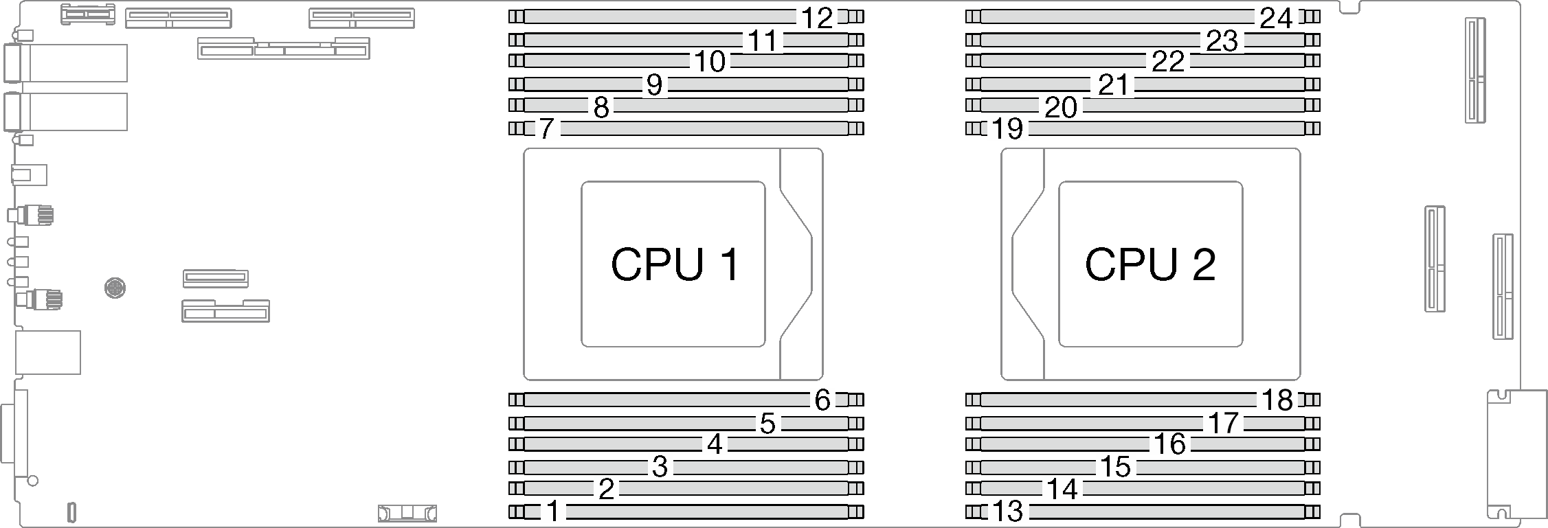
The memory-channel configuration table below shows the relationship between the processors, memory channels, and memory module slot numbers.
| CPU | CPU 1 | |||||||||||
| Channel | F | E | D | C | B | A | G | H | I | J | K | L |
| DIMM slot number | 1 | 2 | 3 | 4 | 5 | 6 | 7 | 8 | 9 | 10 | 11 | 12 |
| CPU | CPU 2 | |||||||||||
| Channel | L | K | J | I | H | G | A | B | C | D | E | F |
| DIMM slot number | 13 | 14 | 15 | 16 | 17 | 18 | 19 | 20 | 21 | 22 | 23 | 24 |
DRAM DIMM installation order for Independent Mode
Mixing DIMM capacity, types, and brand are not allowed. All the DIMM installed in the system must be identical.
Independent memory mode
8 DIMMs per processor, total of 16 DIMMs per node
12 DIMMs per processor, total of 24 DIMMs per node
Independent mode memory population sequence for 8 DIMMs per processor, total of 16 DIMMs per node
| Processor | Processor 1 | |||||||||||
| DIMM slots | 1 | 2 | 3 | 4 | 5 | 6 | 7 | 8 | 9 | 10 | 11 | 12 |
| 8 DIMMs | 2 | 4 | 5 | 6 | 7 | 8 | 9 | 11 | ||||
| Processor | Processor 2 | |||||||||||
| DIMM slots | 13 | 14 | 15 | 16 | 17 | 18 | 19 | 20 | 21 | 22 | 23 | 24 |
| 8 DIMMs | 14 | 16 | 17 | 18 | 19 | 20 | 21 | 23 | ||||
Independent mode memory population sequence for 12 DIMMs per processor, totalof 24 DIMMs per node
| Processor | Processor 1 | |||||||||||
| DIMM slots | 1 | 2 | 3 | 4 | 5 | 6 | 7 | 8 | 9 | 10 | 11 | 12 |
| 12 DIMMs | 1 | 2 | 3 | 4 | 5 | 6 | 7 | 8 | 9 | 10 | 11 | 12 |
| Processor | Processor 2 | |||||||||||
| DIMM slots | 13 | 14 | 15 | 16 | 17 | 18 | 19 | 20 | 21 | 22 | 23 | 24 |
| 12 DIMMs | 13 | 14 | 15 | 16 | 17 | 18 | 19 | 20 | 21 | 22 | 23 | 24 |