Front operator panel LEDs
The front operator panel of the server provides controls and LEDs.
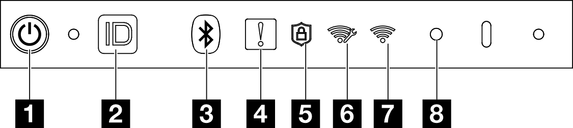
1 Power button with power status LED (green)
You can press the power button to power on the server when you finish setting up the server. You also can hold the power button for several seconds to power off the server if you cannot shut down the server from the operating system. The states of the power LED are as follows:
| Status | Color | Description |
|---|---|---|
| Off | None | No power supply is properly installed, or the LED itself has failed. |
| Flashing rapidly (four times per second) | Green | The server is turned off and is not ready to be turned on. The power button is disabled. This will last approximately 5 to 10 seconds. |
| Flashing slowly (once per second) | Green | The server is turned off and is ready to be turned on. You can press the power button to turn on the server. |
| Lit | Green | The server is turned on. |
2 System ID button with system ID LED (blue)
Use the system ID button and the blue system ID LED to visually locate the server. Each time you press the system ID button, the state of the system ID LED changes. The LED can be changed to on, blinking, or off. You can also use the Lenovo XClarity Controller or a remote management program to change the state of the system ID LED to assist in visually locating the server among other servers.
3 Bluetooth button with LED (blue)
Press the Bluetooth button to enable Bluetooth. After the Bluetooth button is pressed, if SE360 V2 does not pair with any Bluetooth devices within 10 minutes, Bluetooth will be disabled automatically. Identify the status of Bluetooth with the Bluetooth LED.
| Status | Color | Description |
|---|---|---|
| On | Blue | Bluetooth is enabled. |
| Off | None | Bluetooth is disabled, or the server does not come with Bluetooth. |
4 System Error LED (yellow)
The system error LED helps you to determine if there are any system errors.
| Status | Color | Description | Action |
|---|---|---|---|
| On | Yellow | An error has been detected on the server. Causes might include one or more of the following errors:
| Check the Event log to determine the exact cause of the error. |
| Off | None | The server is off or the server is on and is working correctly. | None. |
5 Security LED (green)
- Solid on: The server is operating with security feature enabled.
- Blinking: The server is in System Lockdown Mode. Activate or unlock the system for operation. See Activate or unlock the system.
- Off: No security feature is enabled on the server.
6 XCC WLAN activity LED (green)
The WLAN activity LED helps you identify the status of WLAN connection.
| Status | Color | Description |
|---|---|---|
| On | Green | There is XCC WLAN connection. |
| Off | None | The is no XCC WLAN connection, or the server does not come with wireless module. |
7 x86 WLAN activity LED (green)
The WLAN activity LED helps you identify the status of WLAN connection.
| Status | Color | Description |
|---|---|---|
| On | Green | The x86 WLAN is operating properly. |
| Off | None | The x86 WLAN RF is turned off, or the x86 WLAN is not operating properly, or the server does not come with wireless module. |
8 NMI button
Press this button to force a nonmaskable interrupt to the processor. You might have to use a pen or the end of a straightened paper clip to press the button. You can also use it to force a blue-screen memory dump. Use this button only when you are directed to do so by Lenovo Support.