7mm trayless drives
See this topic to learn how to do the cable routing corresponding to the system configuration.
7mm SAS/SATA drives
Follow the cable routing plan corresponding to the planned configuration.
7mm SATA drives without AnyBay drive cage (onboard SW RAID)
Figure 1. Cable routing for four 7mm drives (SATA, without AnyBay drive cage)
| From | To | |
| 1 | 7mm drives (Drive 0, 2) | Drive power connector 2
|
| 2 | 7mm drives (Drive 1, 3) | Drive power connector 1 |
| 3 | 7mm drives (Drive 0 to 3) | SATA connector (0 to 3) |
7mm SATA drives with AnyBay drive cage (onboard SW RAID)
Figure 2. Cable routing for four 7mm drives (SATA, with AnyBay drive cage)
| From | To | |
| 1 | 7mm drives (Drive 0 to 3) | Drive power connector 2
|
| 2 | 7mm drives (Drive 0 to 3) | SATA connector (0 to 3) |
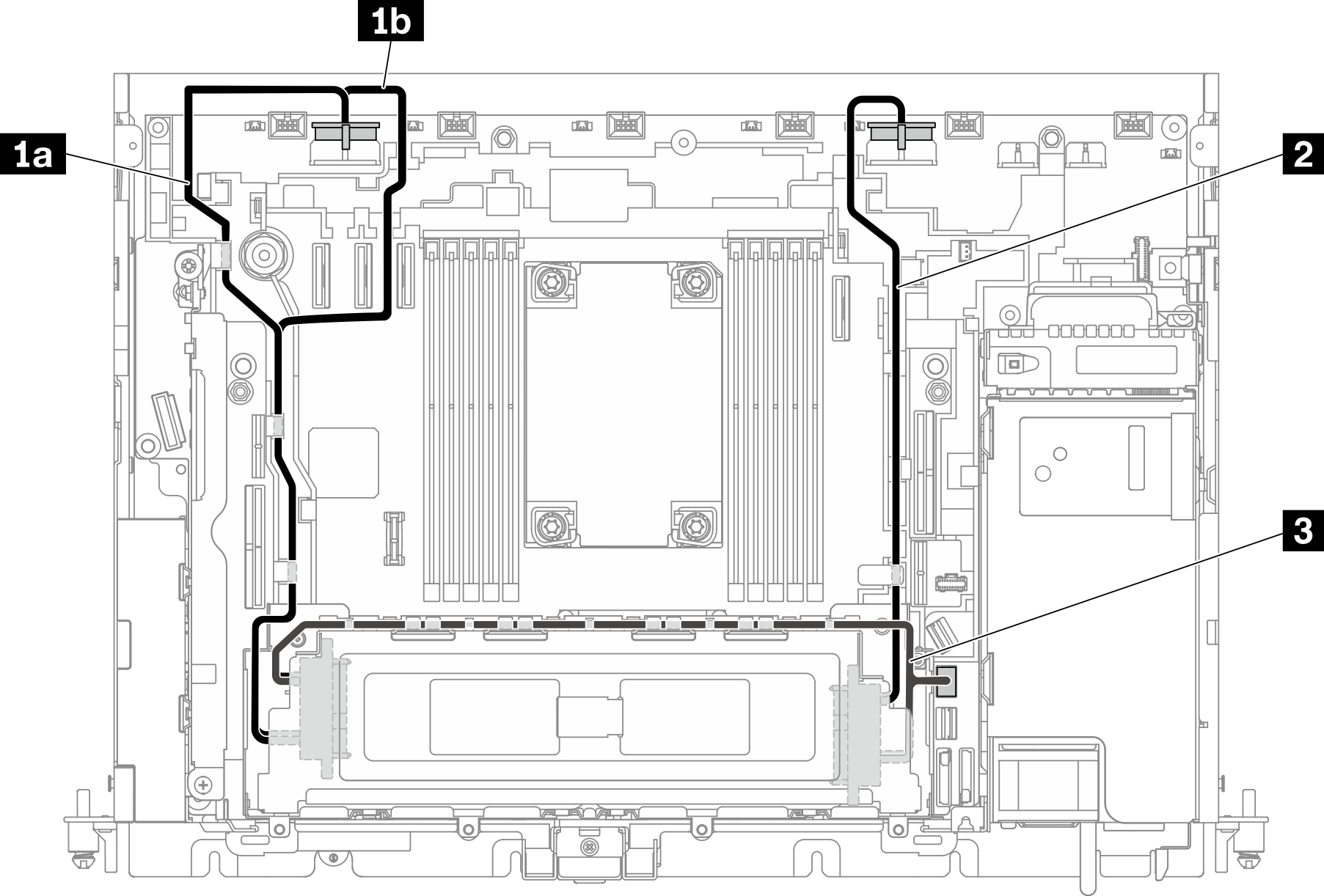
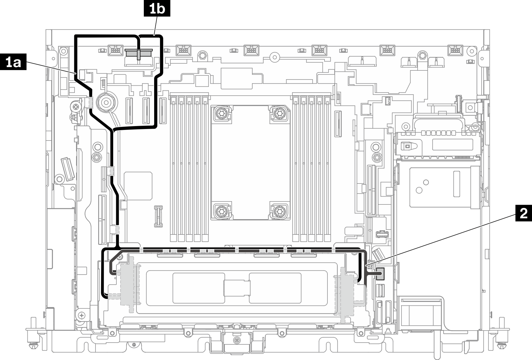
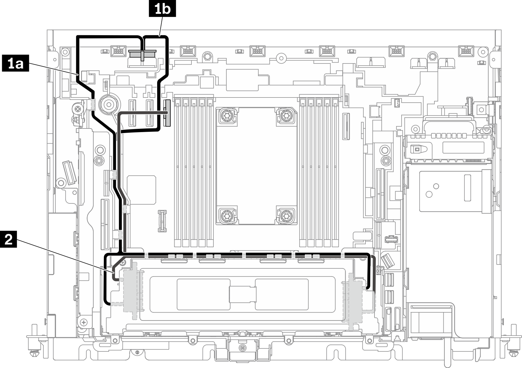
7mm SAS/SATA drives with hardware RAID adapter
Figure 3. SAS/SATA and power cable for 7mm drives
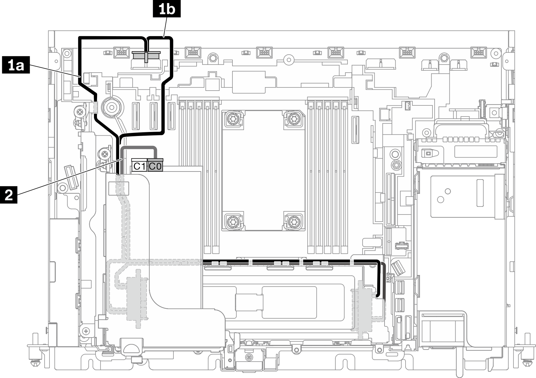
Note
- The RAID adapter must be installed in Slot 6 of Riser 1.
- Connect 1a or 1b first, and proceed to install Riser 1 (see Install half-length adapters and riser assemblies), and connect 2.
| From | To | |
| 1 | 7mm drives (Drive 0 to 3) | Drive power connector 2
|
| 2 | 7mm drives (Drive 0 to 3) | C0 connector on RAID adapter (PCIe Slot 6) |
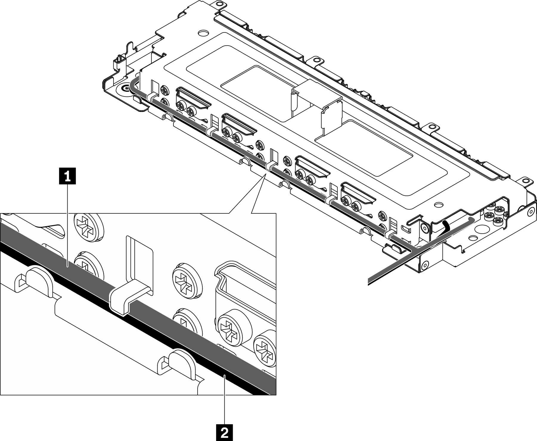
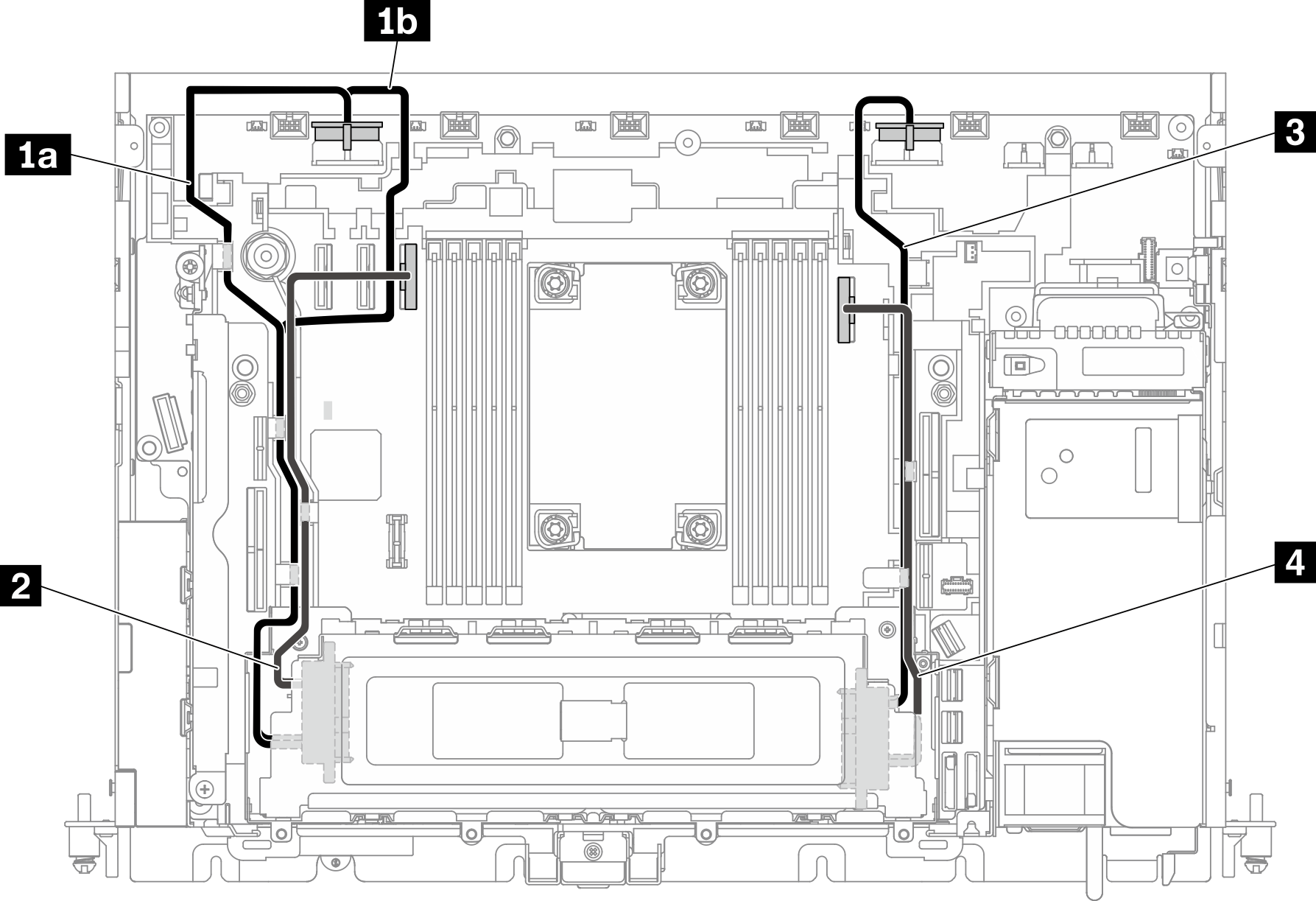
Note
When routing cables along the side of the drive cage, make sure to route the 2 power cable into the clips before 1 signal cable.
Figure 4. Cable routing along the trayless drive cage
7mm NVMe drives
Follow the cable routing plan corresponding to the planned configuration.
One or two 7mm NVMe drives
Figure 5. Cable routing for one or two 7mm drives (NVMe)
| From | To | |
| 1 | 7mm drives (Drive 0, 1) | Drive power connector 2
|
| 2 | 7mm drives (Drive 0, 1) | PCIe connector 3 |
Three or four 7mm NVMe drives
Note
When adopting this plan, hot-swap drive cage in riser 2 is not supported.
Figure 6. Cable routing for three or four 7mm drives (NVMe)
| From | To | |
| 1 | 7mm drives (Drive 0, 2) | Drive power connector 2
|
| 2 | PCIe connector 3 | |
| 3 | 7mm drives (Drive 1, 3) | Drive power connector 1 |
| 4 | PCIe connector 2 |
Give documentation feedback