Install the PCIe adapters and riser assemblies
See this topic to learn how to install the PCIe adapters and riser assemblies.
About this task
- Before installing the PCIe riser assemblies, make sure to complete installation and cable routing of trayless drives and the drive cage.
- Make sure the required PCIe cables for the planned configuration are connected to the risers. See Cable routing for PCIe riser assemblies and hot-swap drives.
- Full-length adapters are supported in the configurations with 1U heat sink installed in 360mm chassis. Make sure the adapter to be installed is supported in the selected configuration.
- Proceed to the corresponding topic to the type of PCIe adapters to be installed.
Install half-length adapters and riser assemblies
Procedure
- If necessary, install the PCIe riser-card to the riser.
Riser 1
Secure the riser card to the riser with three screws.Figure 1. Installing the riser-card to Riser 1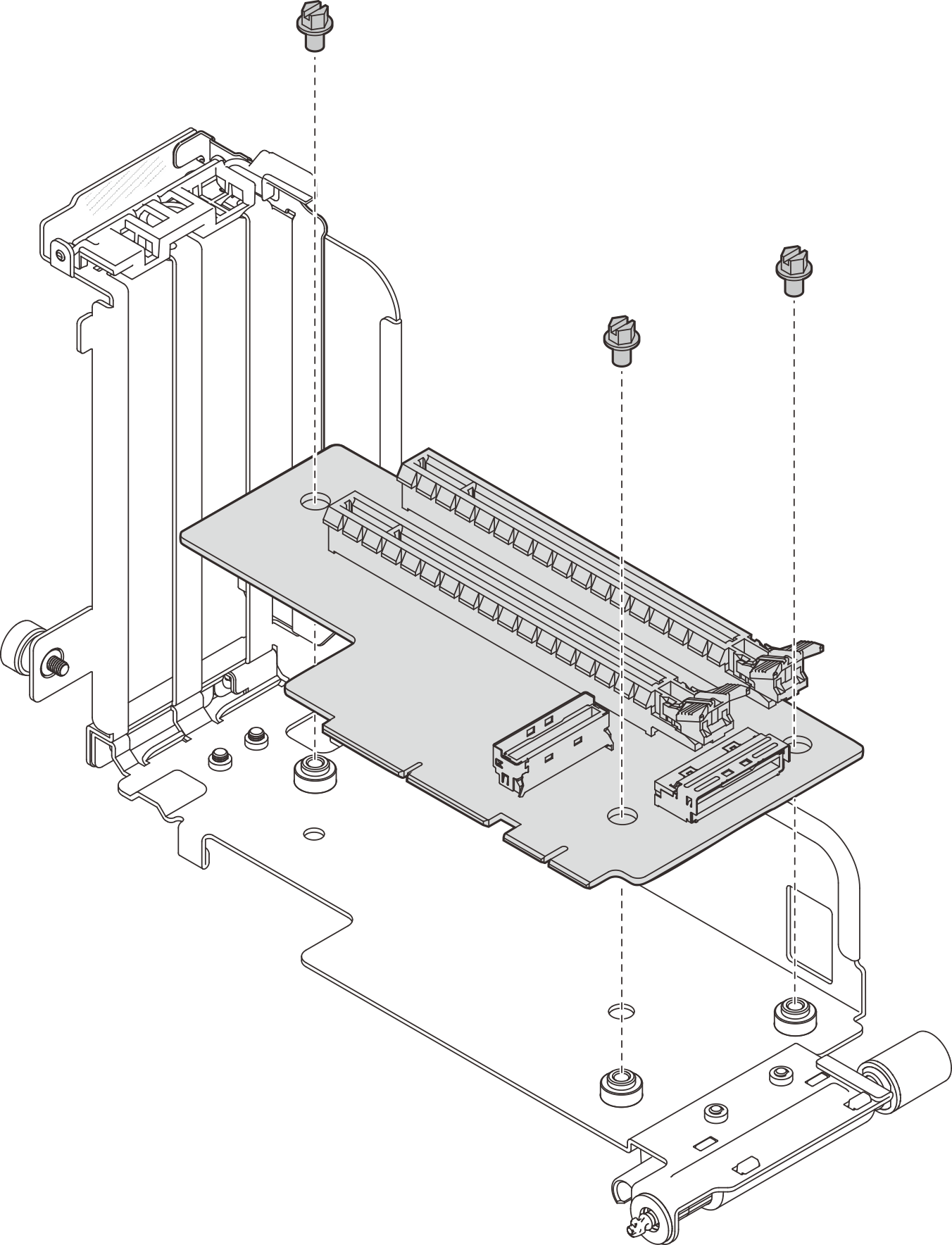
Riser 2
Secure the riser card to the riser with four screws.Figure 2. Installing the riser-card to Riser 2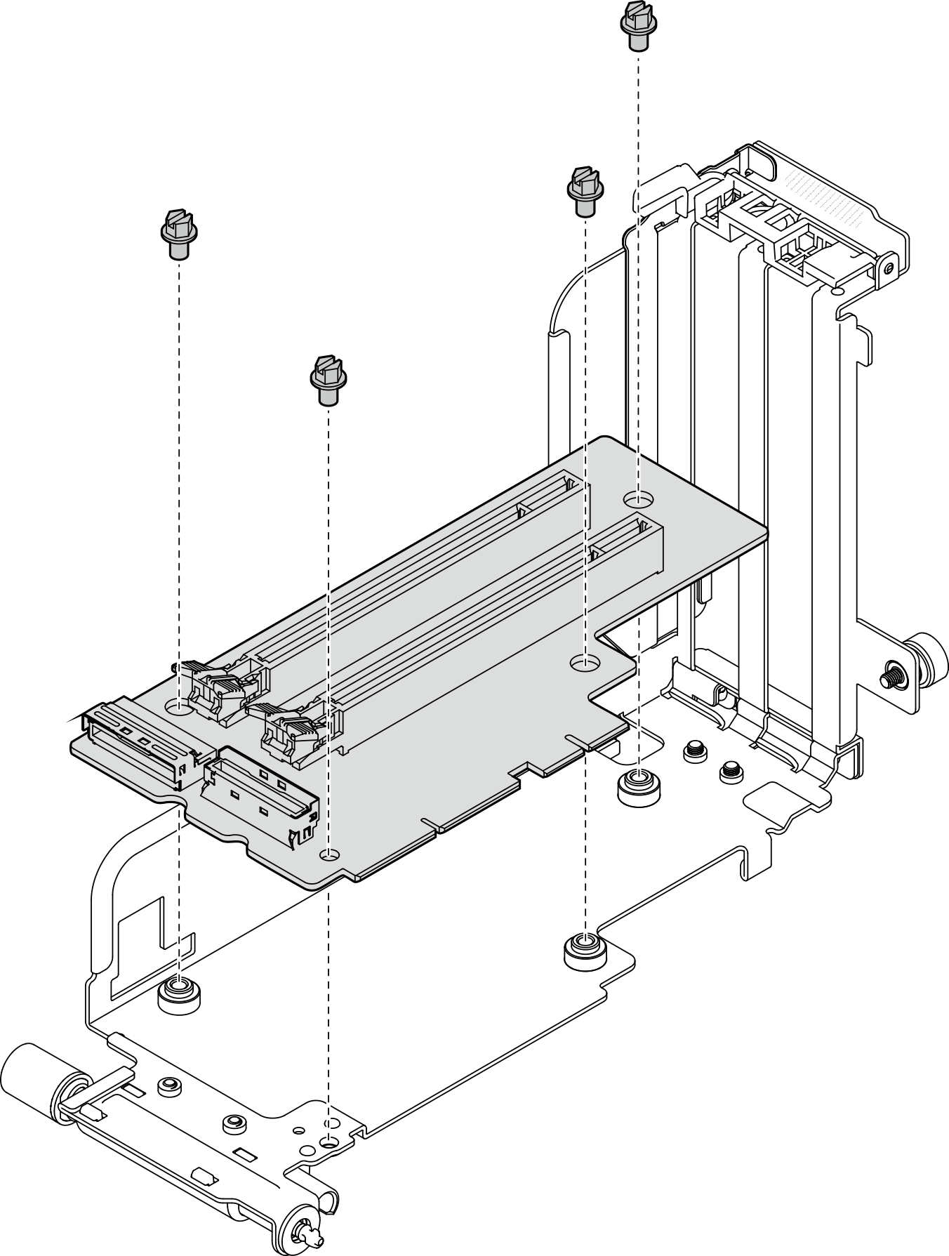
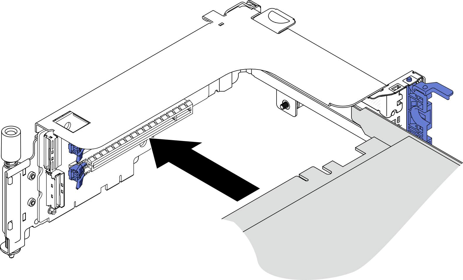
- Align the adapter with the connector in the riser assembly, and push it in until the latch clicks in the lock position.Figure 3. Installing an adapter to the riser
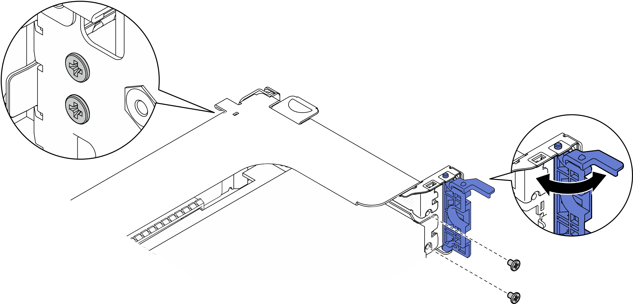
- Secure the adapter with screws and close the retaining latch. Two spared screws are available on the side of the riser.Figure 4. Securing an adapter to the riser
- Lower the riser assembly until it is firmly seated; then, tighten the two captive screws to secure it to the chassis.Figure 5. Installing PCIe Riser 1
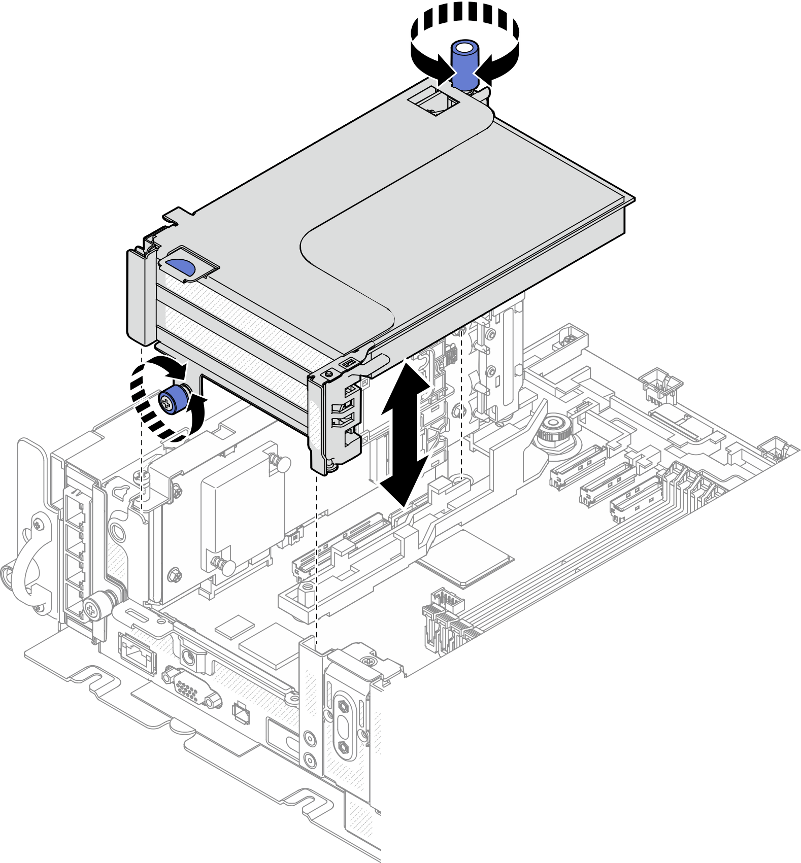 Figure 6. Installing PCIe Riser 2
Install PCIe Riser 2 with AnyBay drive cage
Procedure
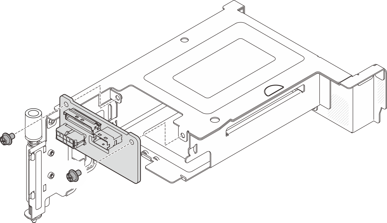
- If necessary, secure the AnyBay drive backplane to the riser cage with two screws.Figure 7. Installing the AnyBay backplane to the drive cage
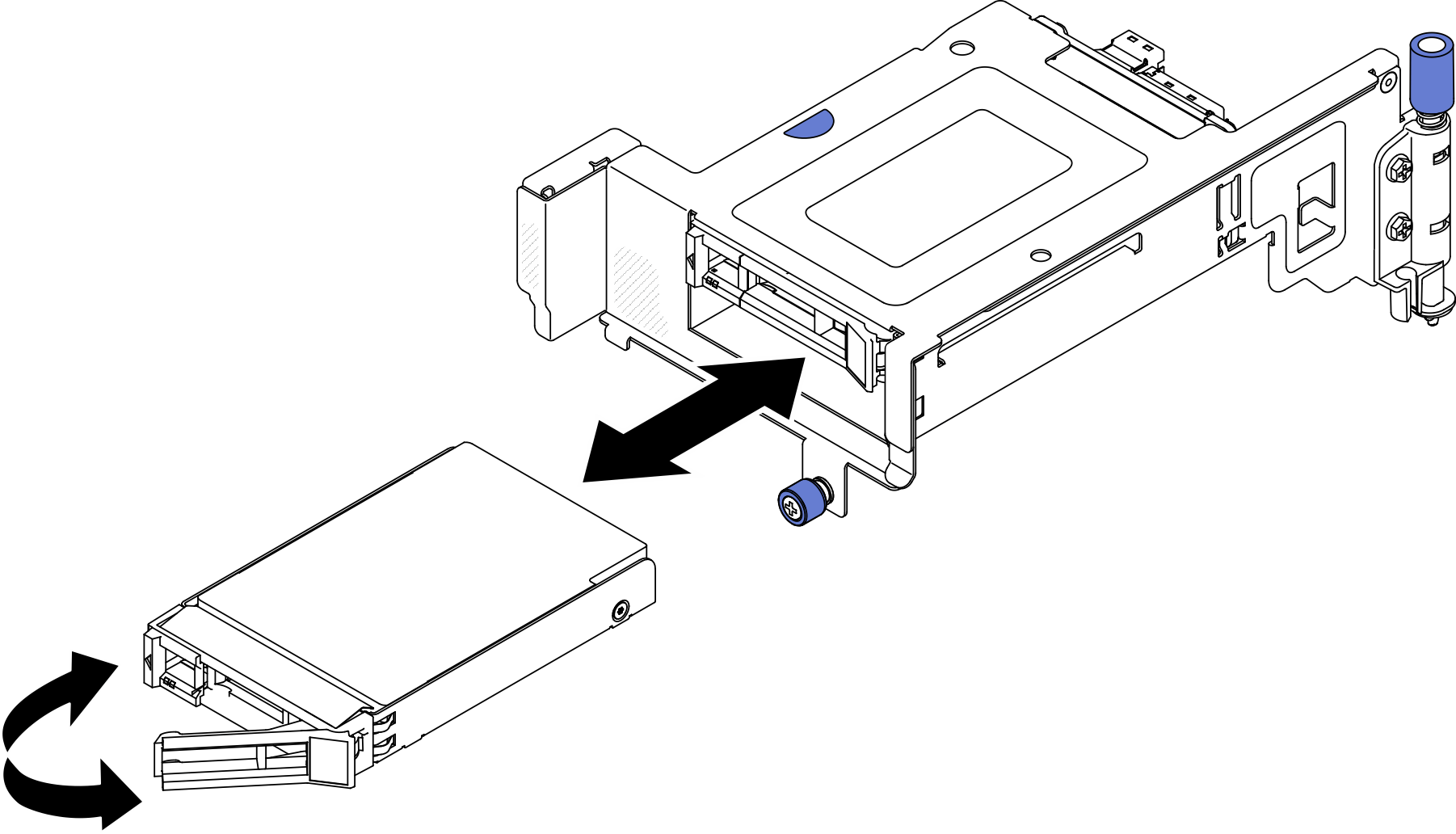
- Gently rotate the release latch away to unlock the drive handle; then, slide the drive into the drive bay until it stops, and rotate the handle back to the locked position.Figure 8. Installing the hot-swap drives
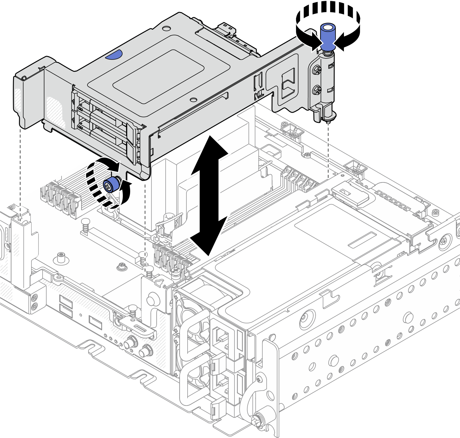
- Lower the riser assembly until it is firmly seated; then, tighten the two captive screws to secure it to the chassis.Figure 9. Installing PCIe riser 2 with AnyBay drive cage
Install full-length adapters and riser assemblies (360mm chassis)
Full-length adapters are supported in the configurations with 1U heat sink installed in 360mm chassis. Make sure the adapter to be installed is supported in the selected configuration.
Double-width full-length GPU adapter is supported in PCIe Slot 4, Slot 5. (Installation order: Slot 4 >> 5.)
- ThinkSystem Intel Flex 170 16GB Gen4 Passive GPU is supported in PCIe slots in the following configurations:
- x16/x16 + x8/x16: Slot 3
- x16/x8 + AnyBay: Slot 6
- x16/x8 + x8/x16: Slot 6, Slot 3 (Installation order: Slot 6 >> 3)
- x16/x16 + x16/x16: Slot 3
Procedure
- If necessary, install the PCIe riser-card to the riser.
Riser 1
Secure the riser card to the riser with three screws.Figure 10. Installing the riser-card to Riser 1Riser 2
Secure the riser card to the riser with four screws.Figure 11. Installing the riser-card to Riser 2
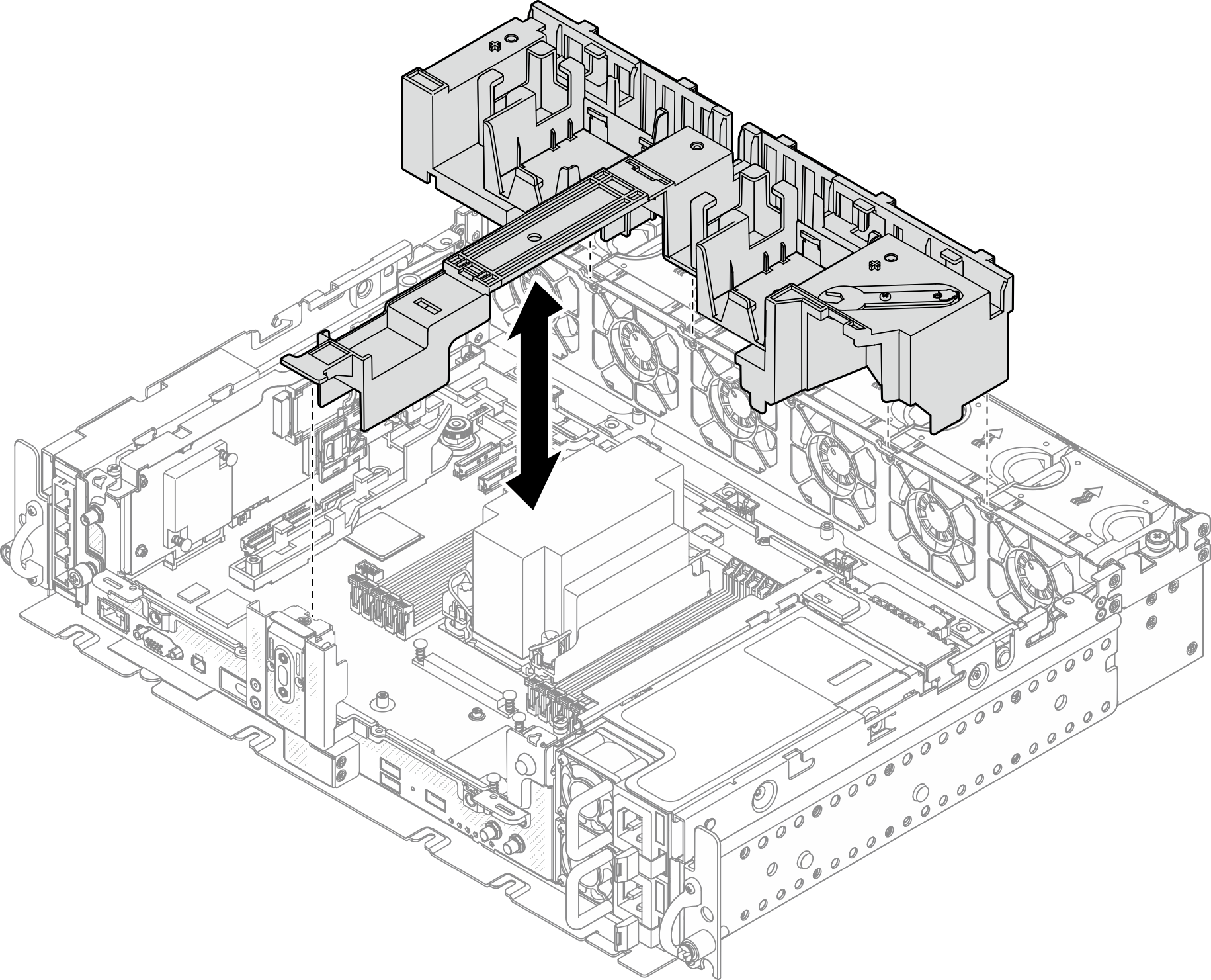
- Make sure the air baffle is installed before installing the PCIe riser assemblies.Figure 12. Installing the air baffle
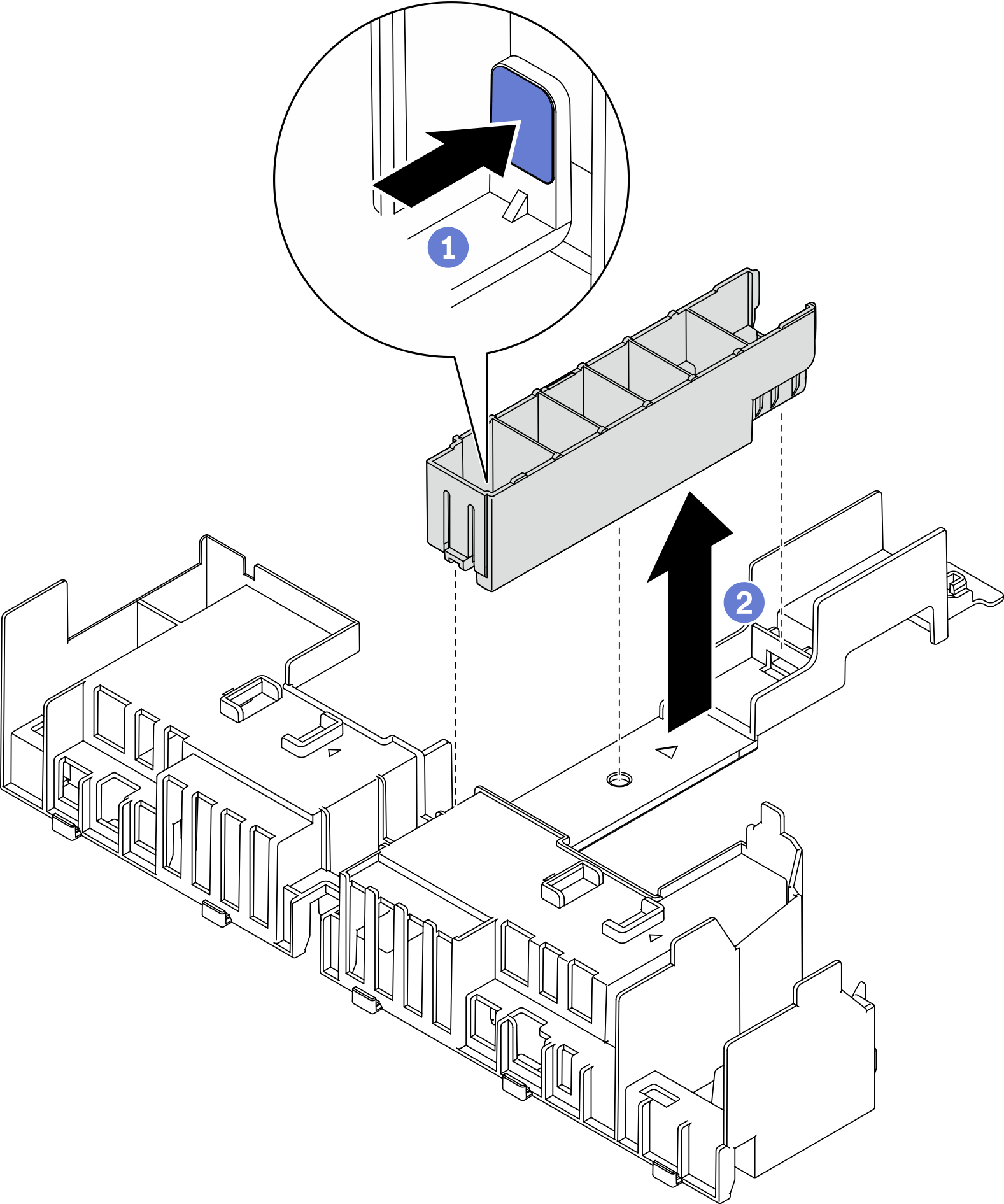
 Note
Note- If the heat sink is 1U, make sure the heat sink filler is installed to the air baffle.Figure 13. Installing the heat sink filler
- Align the adapter with the connector in the riser assembly, and push it in until the latch clicks in the lock position.Figure 14. Installing an adapter to the riser
- Secure the adapter with screws and close the retaining latch. Two spared screws are available on the side of the riser.Figure 15. Securing an adapter to the riser
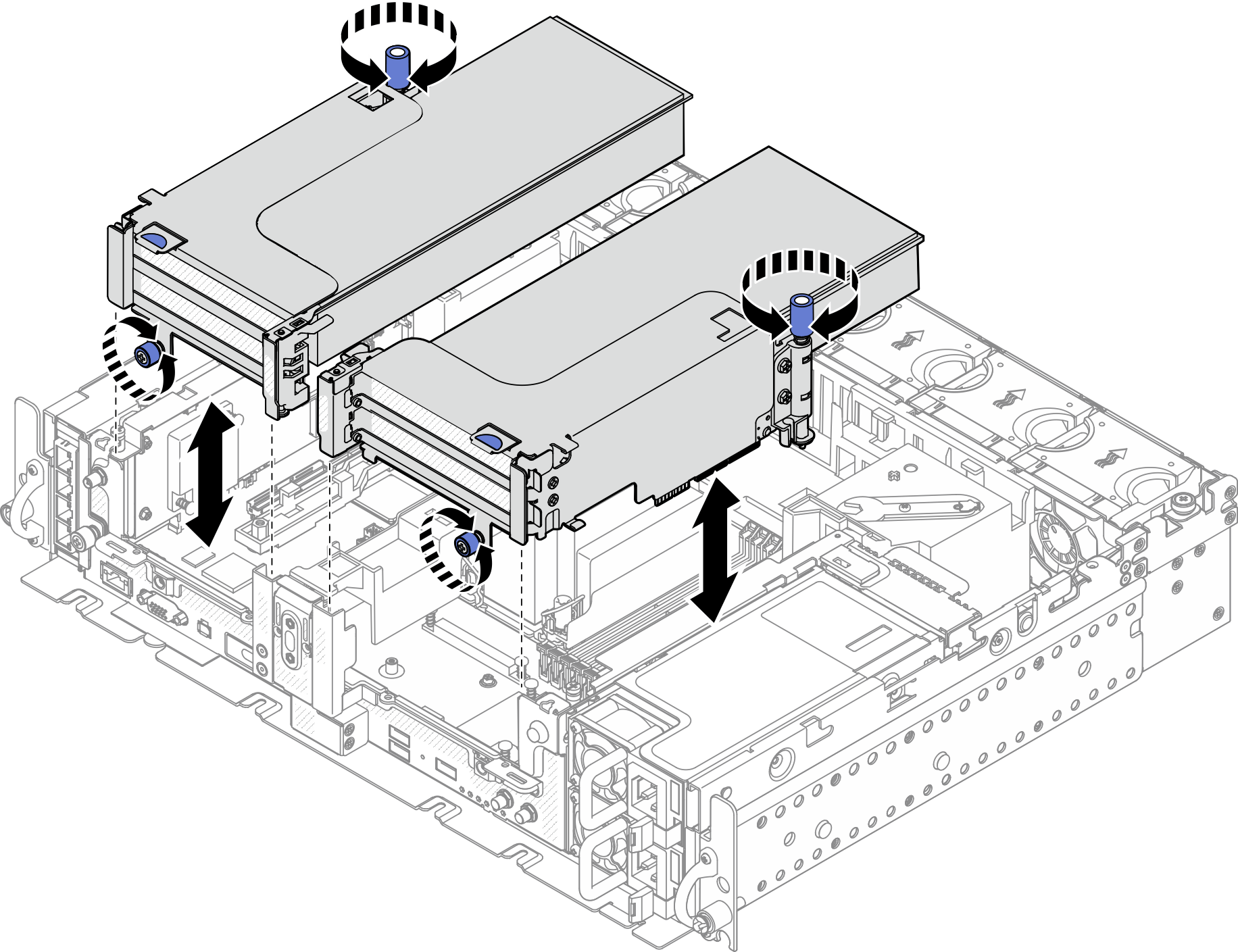
- Lower the riser assembly until it is firmly seated; then, tighten the two captive screws to secure it to the chassis.Figure 16. Installing the riser assemblies
- Route the GPU power cables as illustrated.Figure 17. Cable routing for full-length GPU power cables
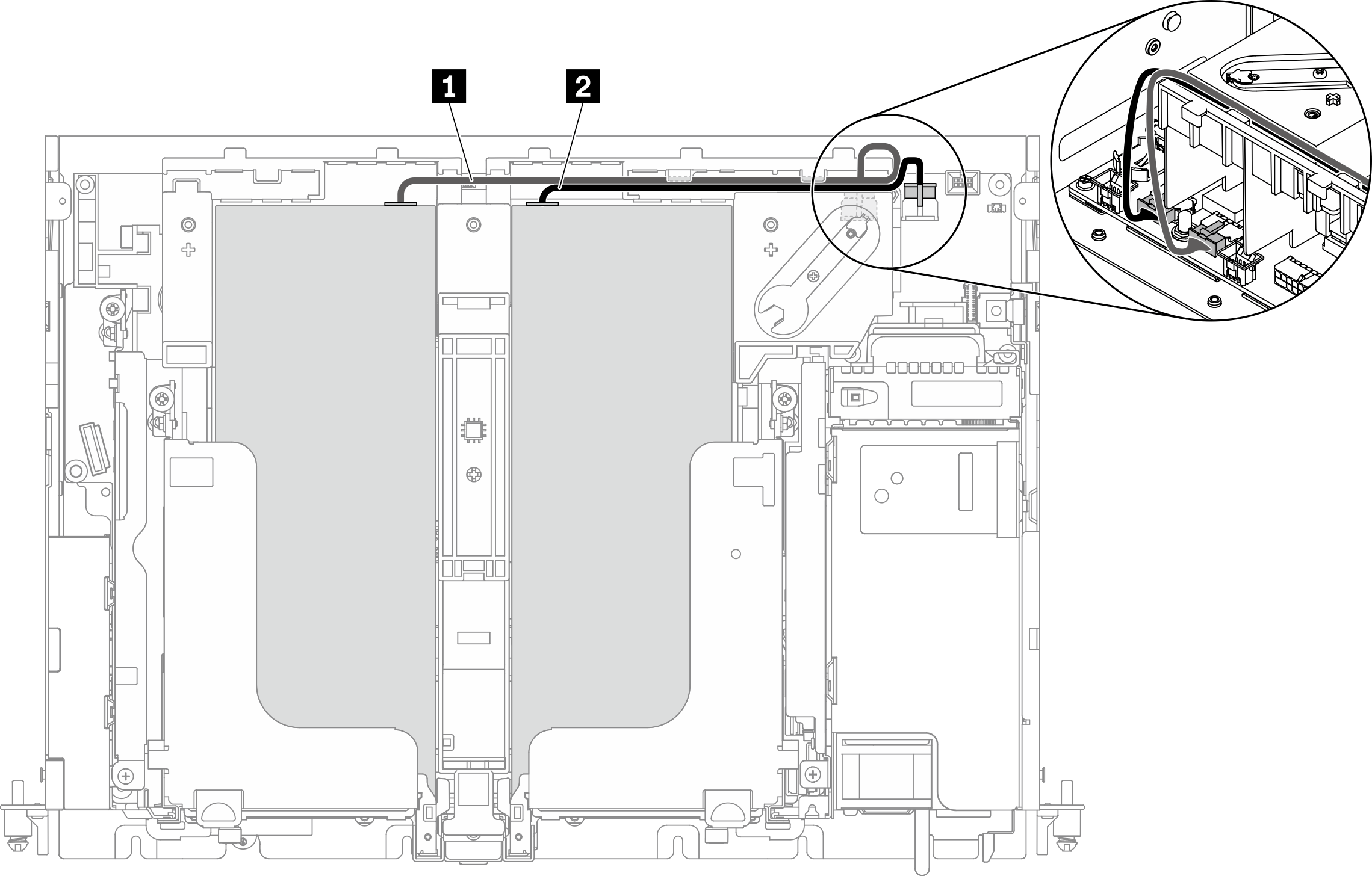 Note
Note- Make sure 1 goes on top of 2.
- Make sure to secure the power cables along the channel on the air baffle.
Table 1. Power cable routing for adapters From To 1 GPU in Slot 5 or Slot 6, Riser 1 GPU power connector 2 2 GPU in Slot 4 or Slot 3, Riser 2 GPU power connector 1 - Install the supporting bracket.Figure 18. Installing the supporting bracket
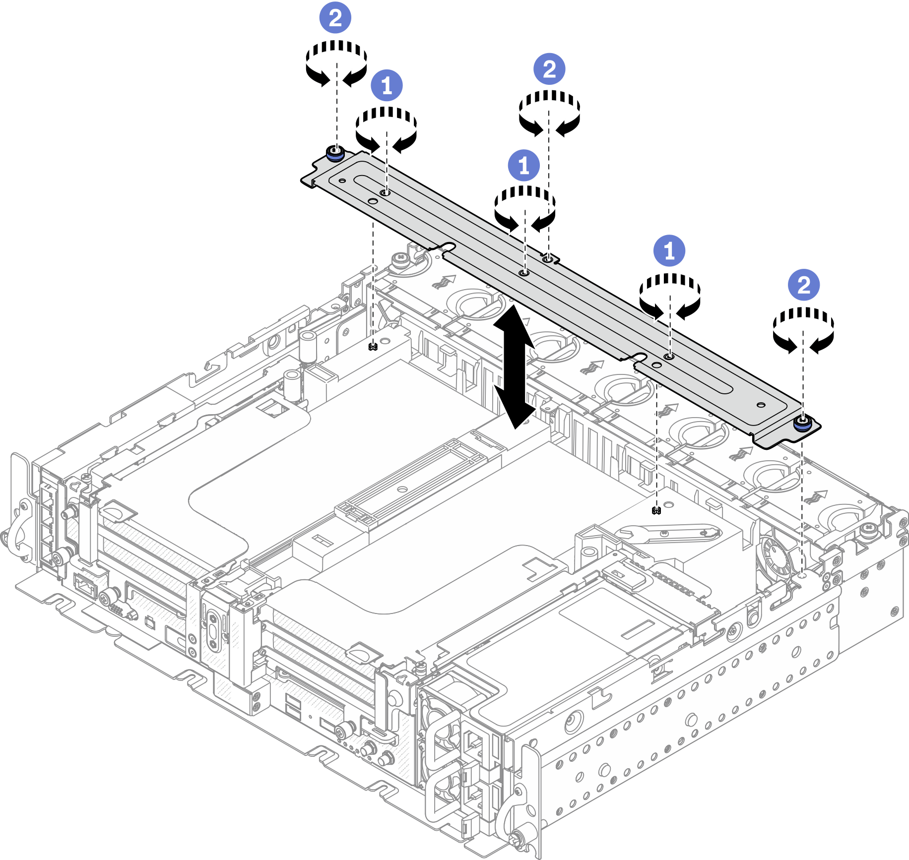
 Tighten the three screws in the middle to secure the supporting bracket from the air baffle.
 Tighten the one captive screw and two thumbscrews to secure the bracket to the chassis.
After this task is completed
Proceed to complete the parts replacement (see Complete the parts replacement).
Give documentation feedback