Cable routing for GPU/FPGA adapter power
See this topic to learn how to do cable routing for GPU adapter or FPGA adapter power.
Adapter power cable routing in 300mm chassis
FPGA power cable routing
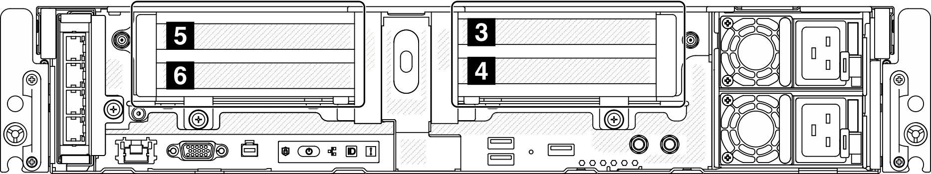
FPGA adapter installation order: Slot 4 >> 3 >> 5 >> 6
| Configuration | Riser 1 | Riser 2 | ||
| x16/x8 + x8/x16 | Slot 5 | x16 PCIe adapter | Slot 3 | x8 PCIe adapter |
| Slot 6 | x8 PCIe adapter | Slot 4 | x16 PCIe adapter | |
| x16/x16 + x16/x16 | Slot 5 | x16 PCIe adapter | Slot 3 | x16 PCIe adapter |
| Slot 6 | x16 PCIe adapter | Slot 4 | x16 PCIe adapter | |
| x16 + x16 | Slot 5 | x16 PCIe adapter | Slot 3 | NA |
| Slot 6 | NA | Slot 4 | x16 PCIe adapter | |
| x16/x16 + x8/x16 | Slot 5 | x16 PCIe adapter | Slot 3 | x8 PCIe adapter |
| Slot 6 | x16 PCIe adapter | Slot 4 | x16 PCIe adapter | |
| x16 + AnyBay | Slot 5 | x16 PCIe adapter | Slot 3 | AnyBay drive cage |
| Slot 6 | NA | Slot 4 | ||
| x16/x16 + AnyBay | Slot 5 | x16 PCIe adapter | Slot 3 | AnyBay drive cage |
| Slot 6 | x16 PCIe adapter | Slot 4 | ||
| x16/x8 + AnyBay | Slot 5 | x16 PCIe adapter | Slot 3 | AnyBay drive cage |
| Slot 6 | x8 PCIe adapter | Slot 4 | ||
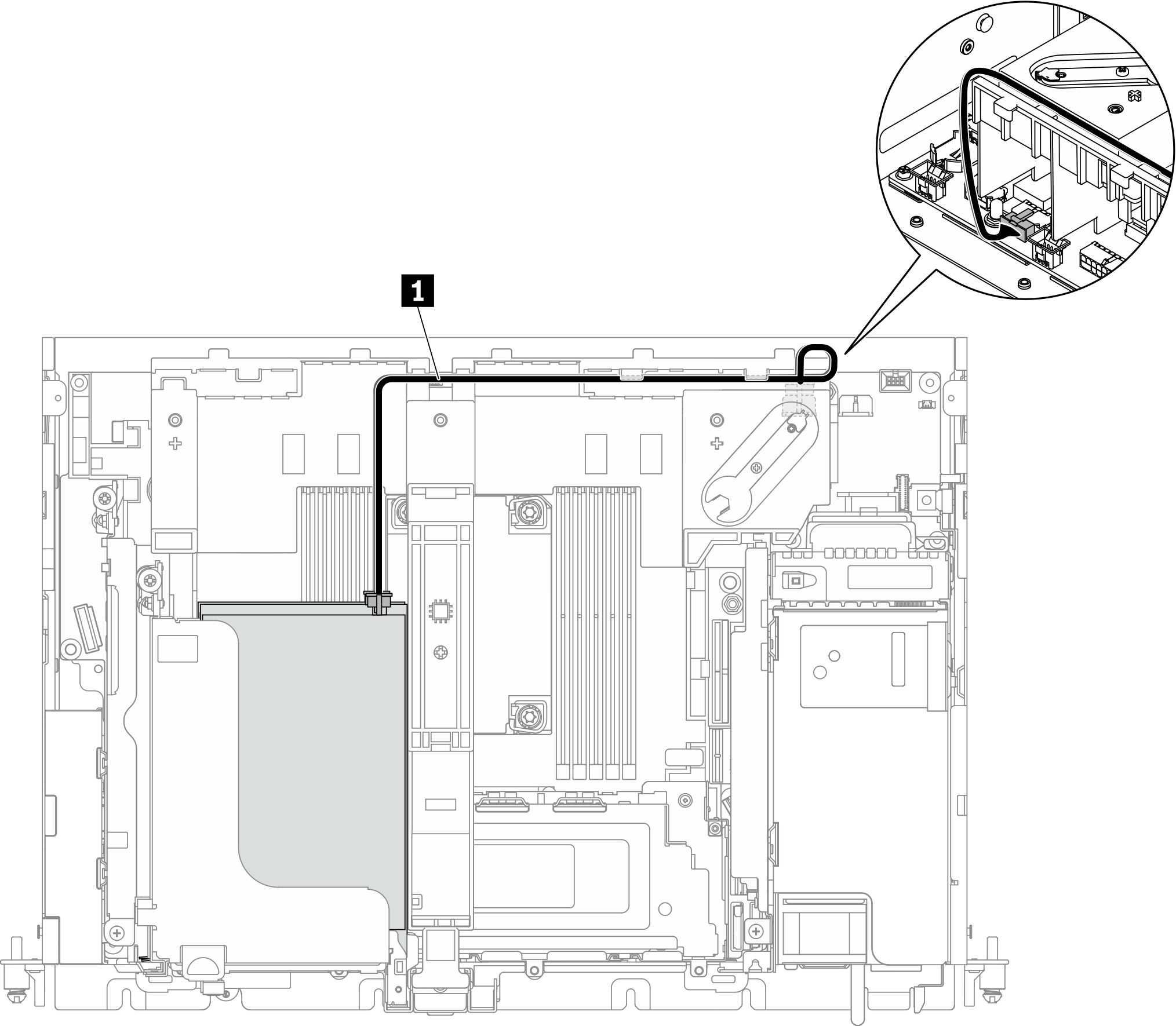
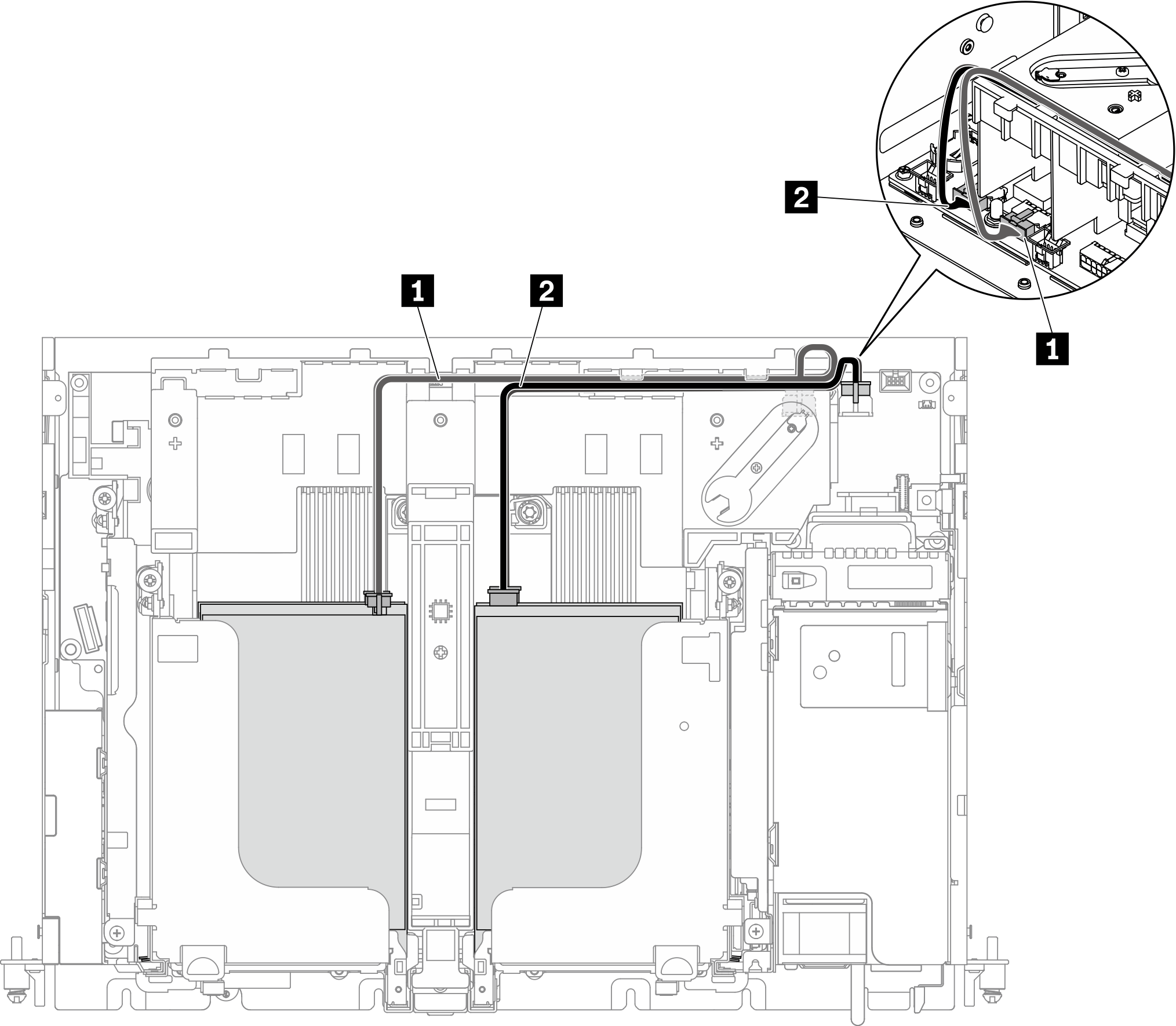
[x16/x8 + x8/x16] or [x16 + x16]
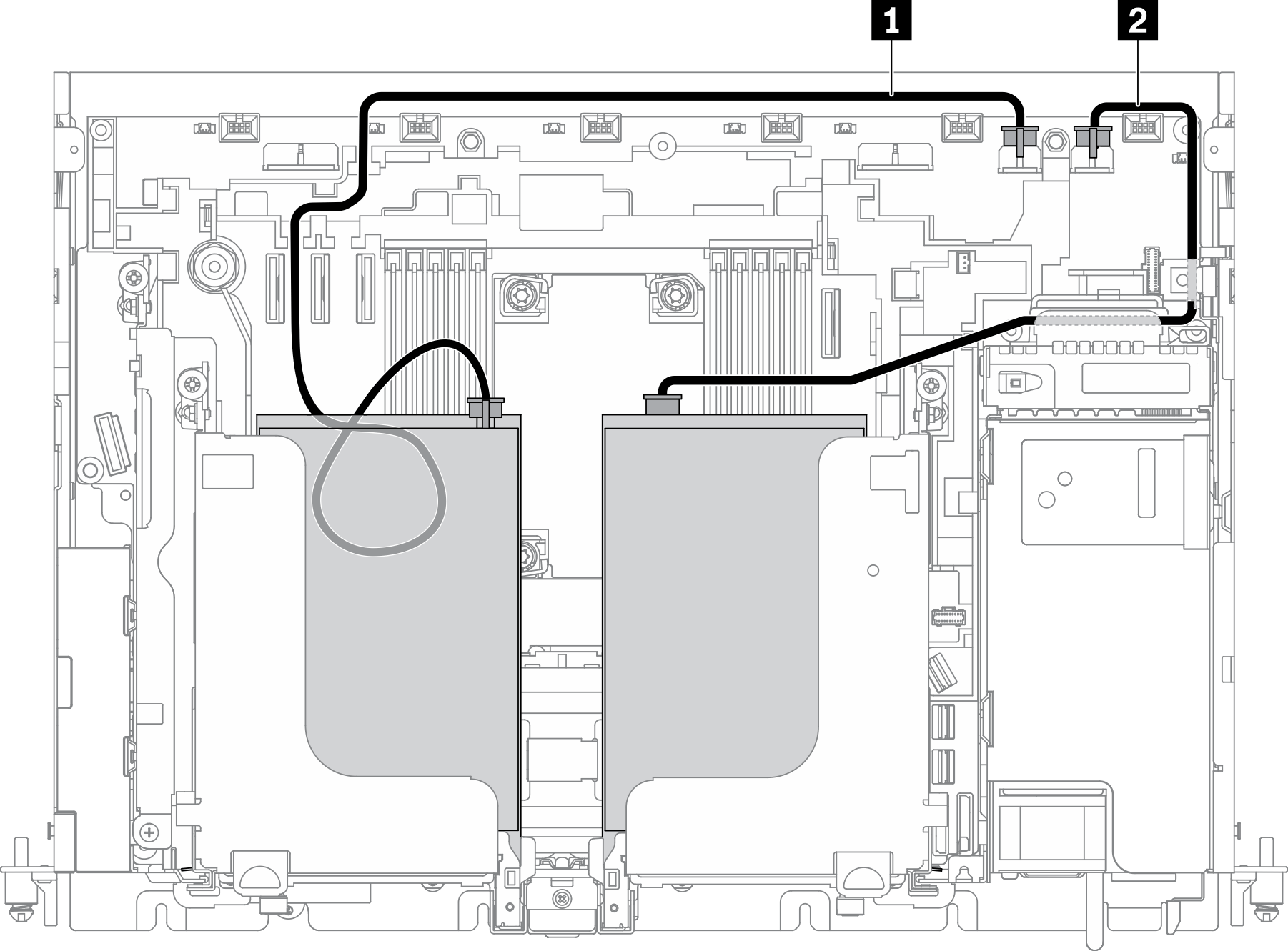 | ||
| From (adapter) | To (on-board) | |
| 1 | PCIe adapter in slot 5, Riser 1 | GPU power connector 2 |
| 2 | PCIe adapter in slot 4, Riser 2 | GPU power connector 1 |
For x16/x8 + x8/x16 configuration, proceed to Riser cable routing for x16/x8 + x8/x16 to connect the riser cables.
No riser cable is required for x16 + x 16 configuration.
x16/x16 + x16/x16
 | ||
| From (adapter) | To (on-board) | |
| 1 | PCIe adapters in slot 5 and 6, Riser 1 | GPU power connector 2 |
| 2 | PCIe adapters in slot 3 and 4, Riser 2 | GPU power connector 1 |
Proceed to Riser cable routing for x16/x16 + x16/x16 to connect the riser cables.
x16/x16 + x8/x16
| ||
| From (adapter) | To (on-board) | |
| 1 | PCIe adapters in slot 5 and 6, Riser 1 | GPU power connector 2 |
| 2 | PCIe adapter in slot 4, Riser 2 | GPU power connector 1 |
Proceed to Riser cable routing for x16/x16 + x8/x16 to connect the riser cables.
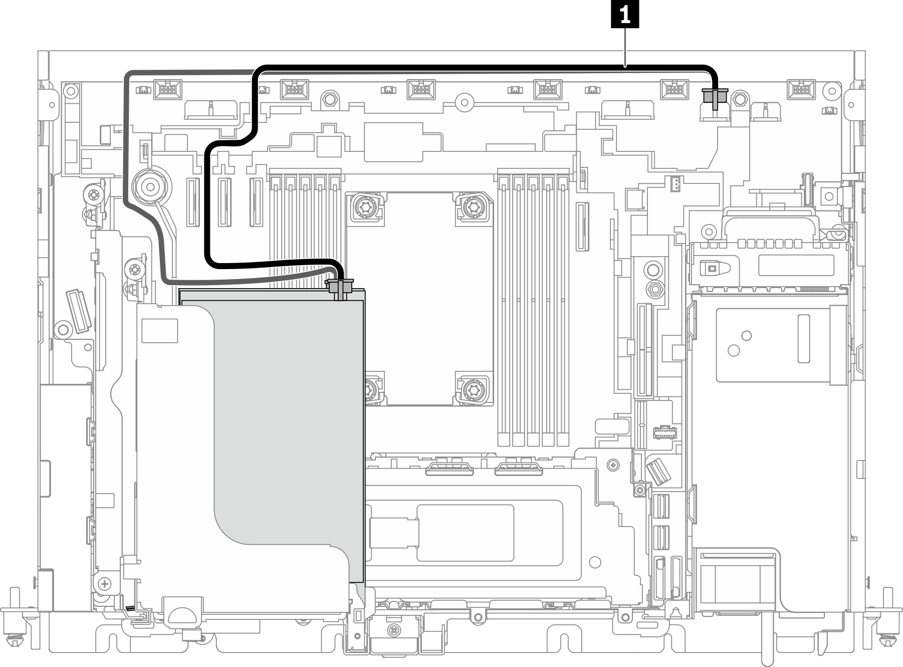
[x16+ AnyBay] or [x16/x8+ AnyBay]
 | ||
| From (adapter) | To (on-board) | |
| 1 | PCIe adapter in slot 5, Riser 1 | GPU power connector 2 |
Proceed to the corresponding section to connect the riser cables.
x16/x16 + AnyBay
 | ||
| From (adapter) | To (on-board) | |
| 1 | PCIe adapters in slot 5 and 6, Riser 1 | GPU power connector 2 |
Proceed to Riser cable routing for x16/x16 + AnyBay to connect the riser cables.
Adapter power cable routing in 360mm chassis
FPGA adapter power cable routing
FPGA adapter installation order: Slot 4 >> 3 >> 5 >> 6
| Configuration | Riser 1 | Riser 2 | ||
| x16 + x16 | Slot 5 | x16 PCIe adapter | Slot 3 | NA |
| Slot 6 | NA | Slot 4 | x16 PCIe adapter | |
| x16 + AnyBay | Slot 5 | x16 PCIe adapter | Slot 3 | AnyBay drive cage |
| Slot 6 | NA | Slot 4 | ||
| x16/x16 + x8/x16 | Slot 5 | x16 PCIe adapter | Slot 3 | x8 PCIe adapter |
| Slot 6 | x16 PCIe adapter | Slot 4 | x16 PCIe adapter | |
| x16/x16 + x16 | Slot 5 | x16 PCIe adapter | Slot 3 | NA |
| Slot 6 | x16 PCIe adapter | Slot 4 | x16 PCIe adapter | |
| x16/x8 + AnyBay | Slot 5 | x16 PCIe adapter | Slot 3 | AnyBay drive cage |
| Slot 6 | x8 PCIe adapter | Slot 4 | ||
| x16/x16 + AnyBay | Slot 5 | x16 PCIe adapter | Slot 3 | AnyBay drive cage |
| Slot 6 | x16 PCIe adapter | Slot 4 | ||
| x16/x8 + x8/x16 | Slot 5 | x16 PCIe adapter | Slot 3 | x8 PCIe adapter |
| Slot 6 | x8 PCIe adapter | Slot 4 | x16 PCIe adapter | |
| x16/x16 + x16/x16 | Slot 5 | x16 PCIe adapter | Slot 3 | x16 PCIe adapter |
| Slot 6 | x16 PCIe adapter | Slot 4 | x16 PCIe adapter | |
[x16 + x16] or [x16/x8 + x8/x16]
 | ||
| From (adapter) | To (on-board) | |
| 1 | PCIe adapter in slot 5, Riser 1 | GPU power connector 2 |
| 2 | PCIe adapter in slot 4, Riser 2 | GPU power connector 1 |
For x16/x8 + x8/x16 configuration, proceed to Riser cable routing for x16/x8 + x8/x16 to connect the riser cables.
No riser cable is required for x16 + x 16 configuration.
[x16 + AnyBay] or [x16/x8 + AnyBay]
 | ||
| From (adapter) | To (on-board) | |
| 1 | PCIe adapter in slot 5, Riser 1 | GPU power connector 2 |
Proceed to the corresponding section to connect the riser cables.
[x16/x16 + x8/x16] or [x16/x16 + x16]
 | ||
| From (adapter) | To (on-board) | |
| 1 | PCIe adapters in slot 5 and 6, Riser 1 | GPU power connector 2 |
| 2 | PCIe adapter in Slot 4 | GPU power connector 1 |
Proceed to the corresponding section to connect the riser cables.
x16/x16 + AnyBay
| ||
| From (adapter) | To (on-board) | |
| 1 | PCIe adapters in slot 5 and 6, Riser 1 | GPU power connector 2 |
Proceed to Riser cable routing for x16/x16 + AnyBay to connect the riser cables.
x16/x16 + x16/x16
| ||
| From (adapter) | To (on-board) | |
| 1 | PCIe adapters in slot 5 and 6, Riser 1 | GPU power connector 2 |
| 2 | PCIe adapters in slot 3 and 4, Riser 2 | GPU power connector 1 |
Proceed to Riser cable routing for x16/x16 + x16/x16 to connect the riser cables.
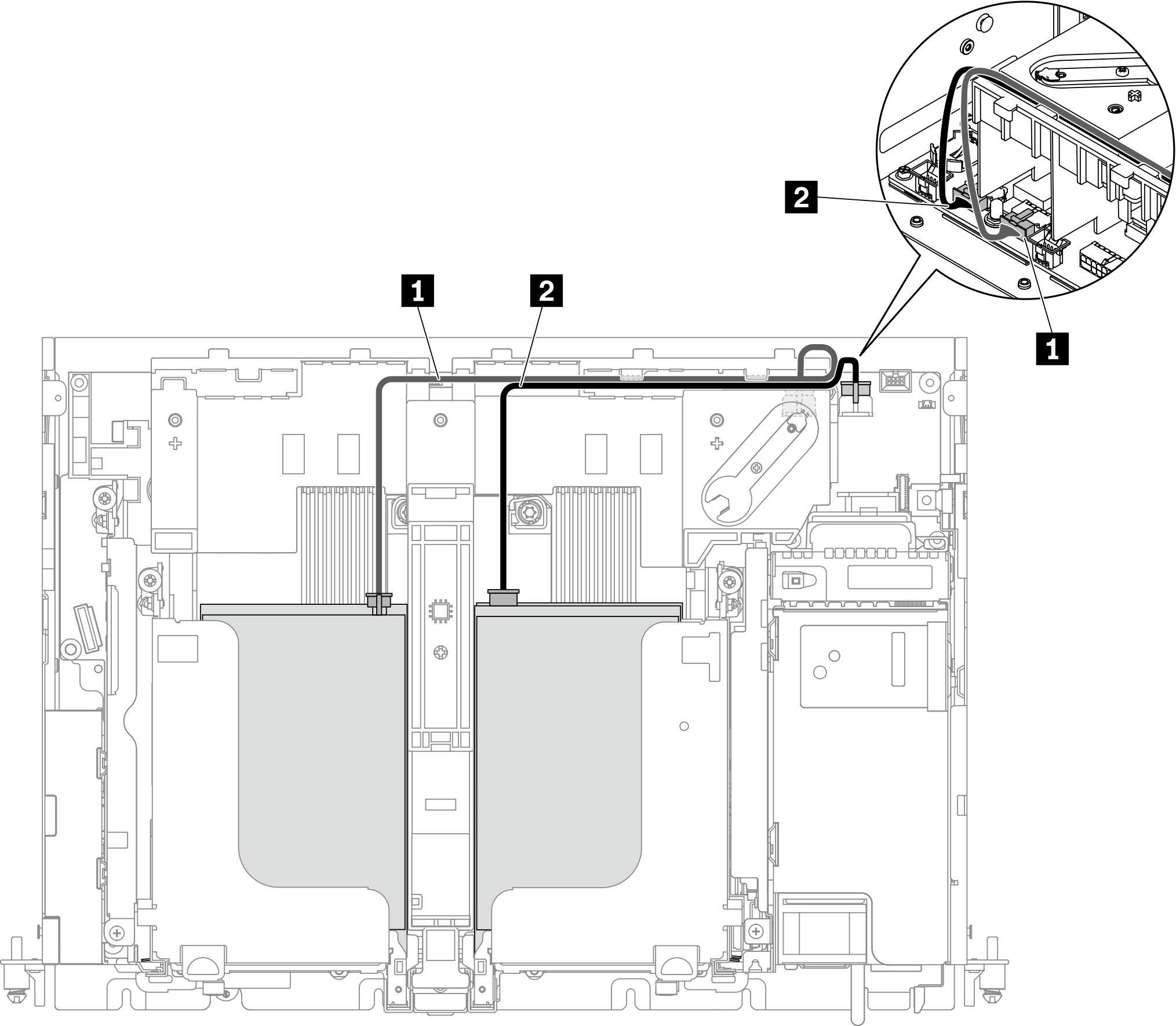
Full-length GPU power cable routing
Double-width full-length GPU adapter is supported in PCIe Slot 4, Slot 5. (Installation order: Slot 4 >> 5.)
- ThinkSystem Intel Flex 170 16GB Gen4 Passive GPU is supported in PCIe slots in the following configurations:
- x16/x16 + x8/x16: Slot 3
- x16/x8 + AnyBay: Slot 6
- x16/x8 + x8/x16: Slot 6, Slot 3 (Installation order: Slot 6 >> 3)
- x16/x16 + x16/x16: Slot 3
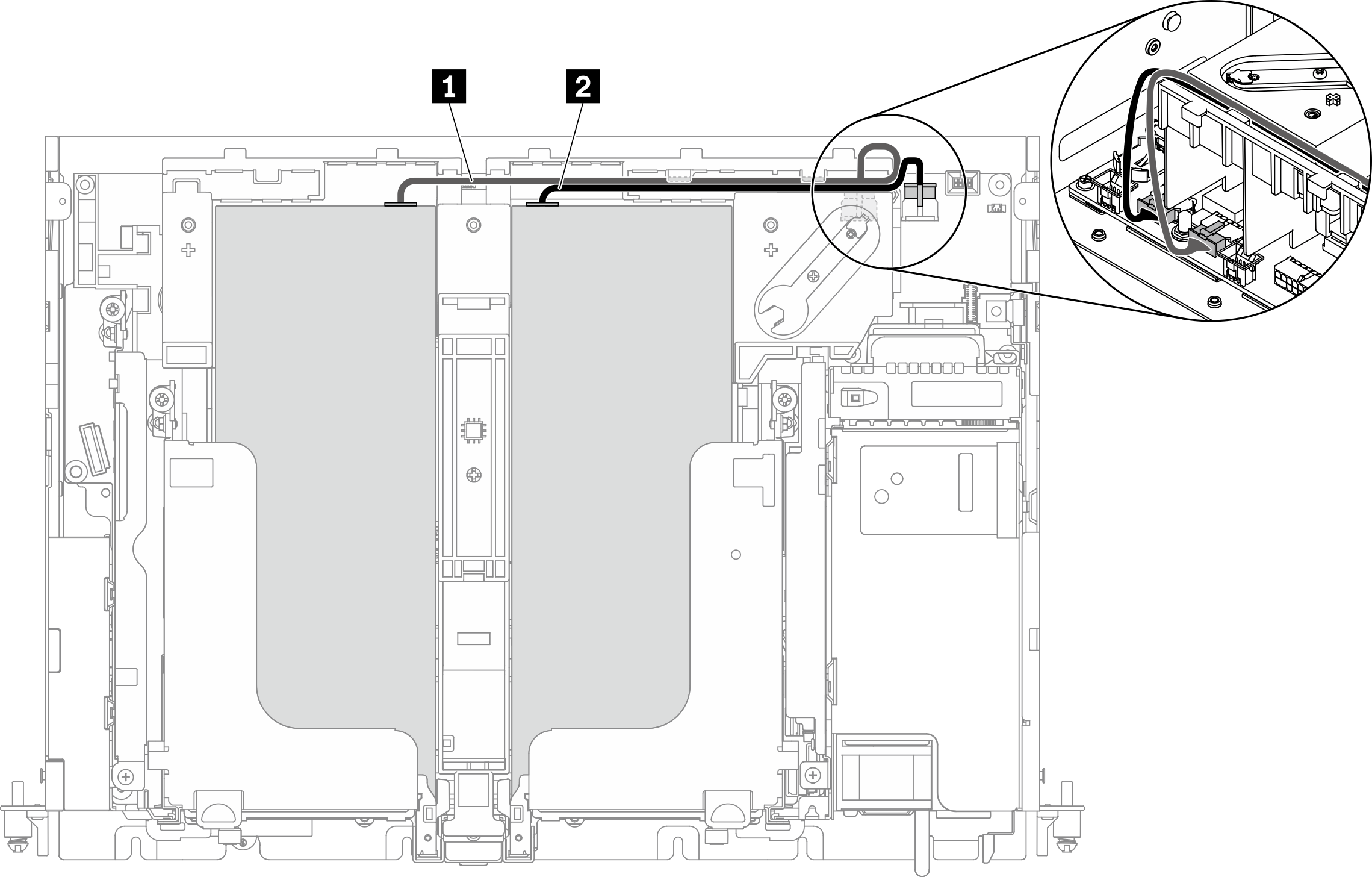
- Make sure 1 goes on top of 2.
- Make sure to secure the power cables along the channel on the air baffle.
| From | To | |
| 1 | GPU in Slot 5 or Slot 6, Riser 1 | GPU power connector 2 |
| 2 | GPU in Slot 4 or Slot 3, Riser 2 | GPU power connector 1 |
Proceed to corresponding section in Cable routing for PCIe riser assemblies and hot-swap drives to connect the riser cables.