Top view
This section contains information on the top view of the server.
Refer to the following table for top view identification of the server
Note
Depending on the configuration, your server might be slightly different from the illustration.
Top view: top layer
The following illustration is the top view after removing the top cover.
Figure 1. Top view: top layer
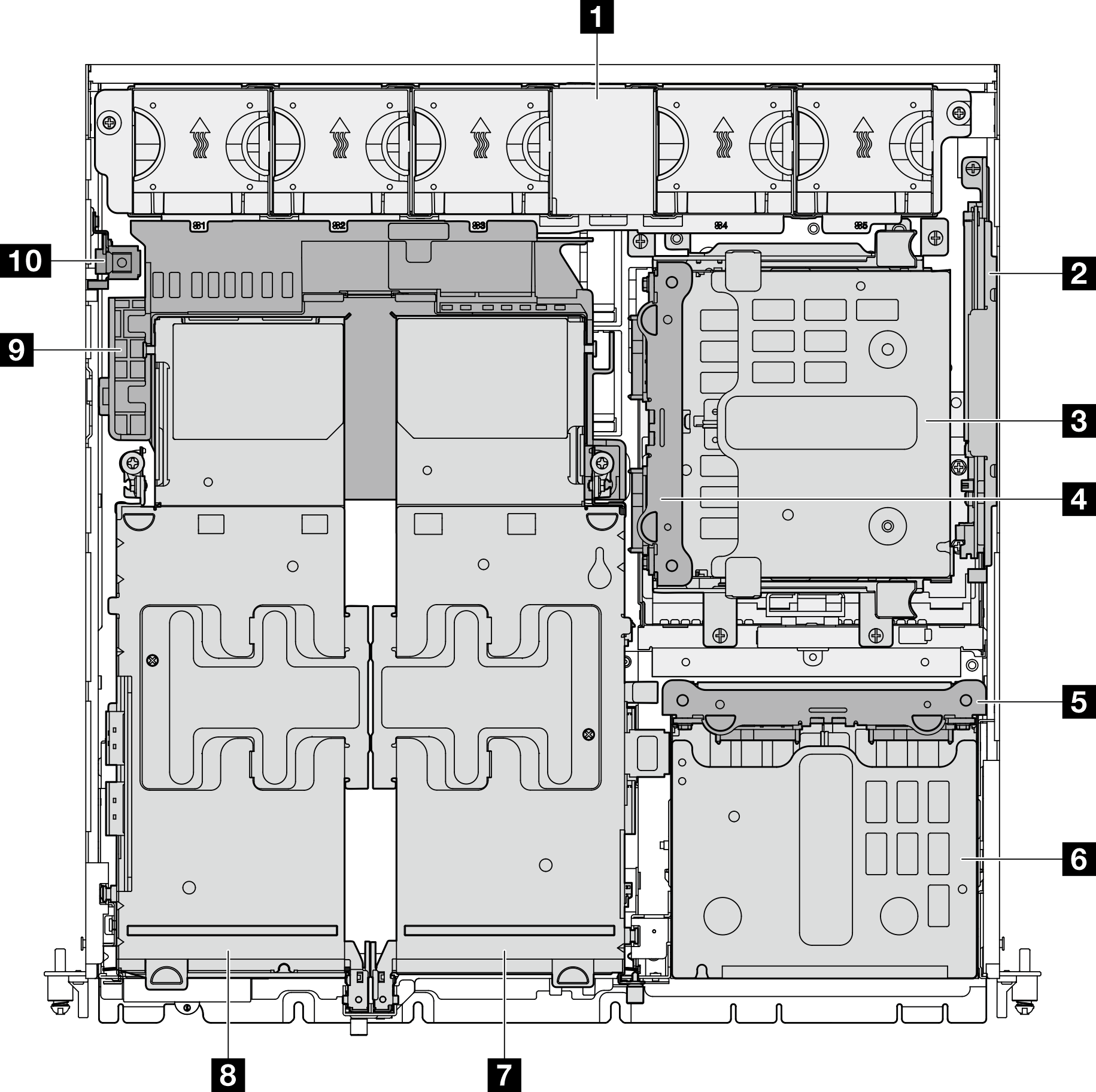
| 1 System fans | 6 Front drive cage |
| 2 (Optional) M.2 backplane assembly | 7 (Optional) PCIe riser 2 |
| 3 (Optional) Internal drive cage | 8 PCIe riser 1 |
| 4 (Optional) Internal drive backplane | 9 Processor air baffle |
| 5 Front drive backplane | 10 Intrusion switch |
Top view: bottom layer
The following illustration is the top view after removing the top cover and the removable components on the top layer.
Figure 2. Top view: bottom layer
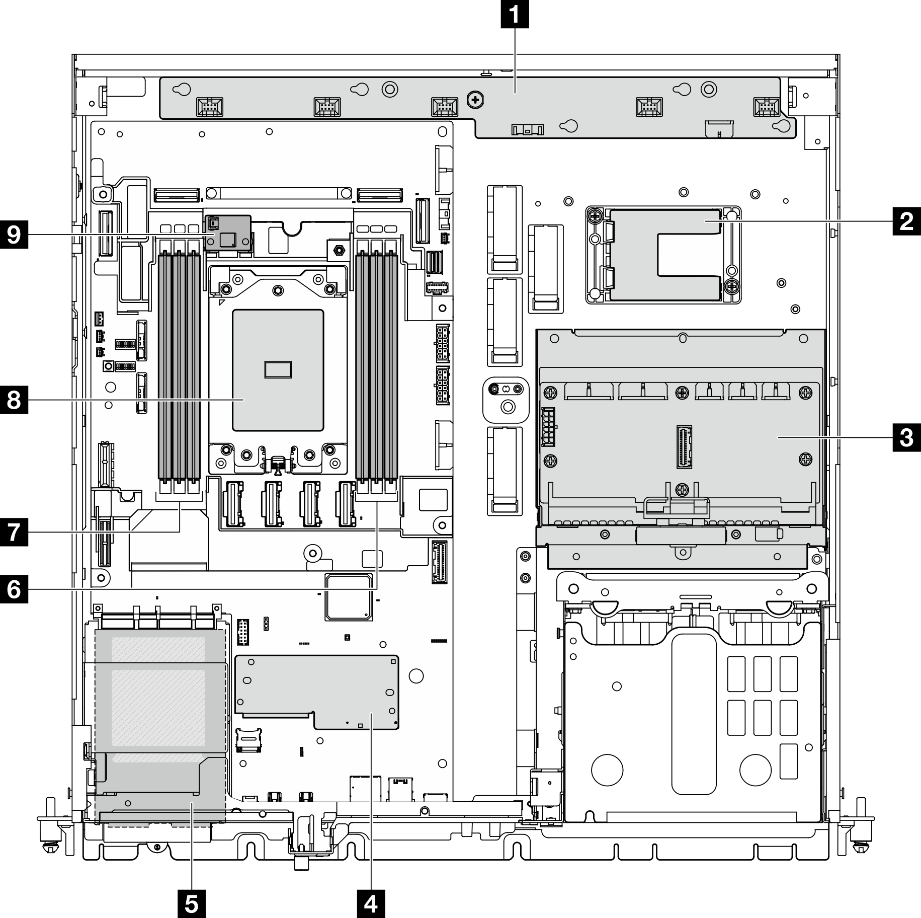
| 1 Fan control board (FCB) | 6 Memory module slots (DIMM 1-3, right to left) |
| 2 RAID flash power module holder Note RAID flash power module (supercap) is an optional part installed in the holder. | 7 Memory module slots (DIMM 4-6, right to left) |
| 3 Power distribution board (PDB) | 8 Processor |
| 4 Firmware and RoT security module | 9 (Optional) Air flow sensor board |
| 5 OCP 3.0 module |
Give documentation feedback