Front view
This section contains information about the controls, LEDs, and connectors on the front of the server.
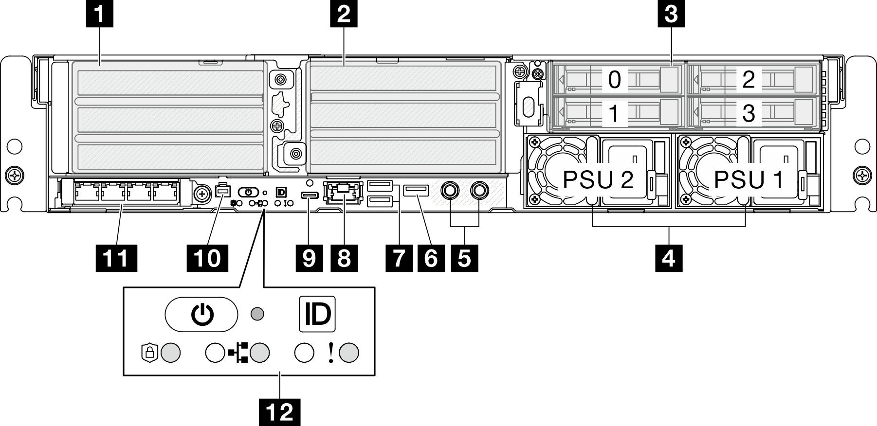
1 / 2 PCIe riser assemblies
Install PCIe adapters into these riser assemblies. See the following table for PCIe slots corresponding to the PCIe riser assembly.
| PCIe riser assembly | PCIe slots (top to bottom) |
|---|---|
| 1 PCIe riser 1 |
Note
|
| 2 PCIe riser 2 Note PCIe riser 2 is optional. The models without PCIe riser 2 come with a riser blank filler. |
Note
|
3 Front drive bays (Bay 0-3)
Install 2.5-inch drives to these bays. See Install a front hot-swap drive for more information.
4 Power supply unit bays (PSU 1-2)
Install power supply units to these bays, and connect power cords to the power supply units. Make sure the power cords are connected properly. SE455 V3 supports the following types of power supplies:
1800-watt Platinum, input power 230 VAC
1100-watt Titanium, input power 230 VAC
1100-watt Platinum, input power 115-230 VAC
1100-watt -48V DC power supply unit
For more information on the power supply LEDs, see Power supply LEDs.
5 Grounding points
Connect the grounding wires to these threaded studs.
6 USB 2.0 Type-A connector with Lenovo XClarity Controller management
Connection to Lenovo XClarity Controller is primarily intended for users with a mobile device running the Lenovo XClarity Controller mobile application. When a mobile device is connected to this USB port, an Ethernet over USB connection is established between the mobile application running on the device and the Lenovo XClarity Controller.
Only one mode is supported:
BMC only mode
In this mode, the USB port is always solely connected to Lenovo XClarity Controller.
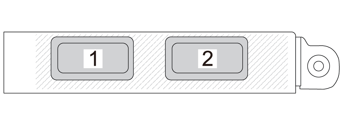
7 USB 3.2 Gen 1 (5 Gbps) Type-A connectors (USB Port 1-2)
Connect a USB device, such as a mouse, keyboard, or other devices, to either of these connectors.
8 XCC system management port (10/100/1000 Mbps RJ-45)
The server has a 1GbE RJ-45 connector dedicated to Lenovo XClarity Controller (XCC) functions. Through the system management port, you can access the Lenovo XClarity Controller directly by connecting your laptop to the management port using an Ethernet cable. Make sure that you modify the IP settings on the laptop so that it is on the same network as the server default settings. A dedicated management network provides additional security by physically separating the management network traffic from the production network.
9 USB 3.2 Gen 1 (5 Gbps) Type-C connector with display support (USB Port 3)
Connect a USB device, such as a mouse, keyboard, monitor, or other devices, to either of this connector. This connector supports display.
10 External diagnostics handset connector
Connect the external diagnostics handset to this connector. See External Diagnostics Handset for more details.
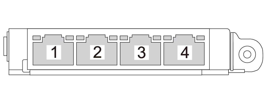
11 OCP 3.0 module (Slot 9)
Slot 9 is with NC-SI support.
12 System buttons and LEDs
Power button with power status LED (green)
Security LED (green)
NMI button
Press this button to force a nonmaskable interrupt to the processor. You might have to use a pen or the end of a straightened paper clip to press the button. You can also use it to force a blue-screen memory dump. Use this button only when you are directed to do so by Lenovo Support.
Network activity LED (green)
System ID button with system ID LED (blue)
- System error LED (yellow)
See Front LEDs for more information.
Front I/O fillers
Install the I/O fillers when the connectors are not used. The connectors could be damaged without proper protection of the fillers.
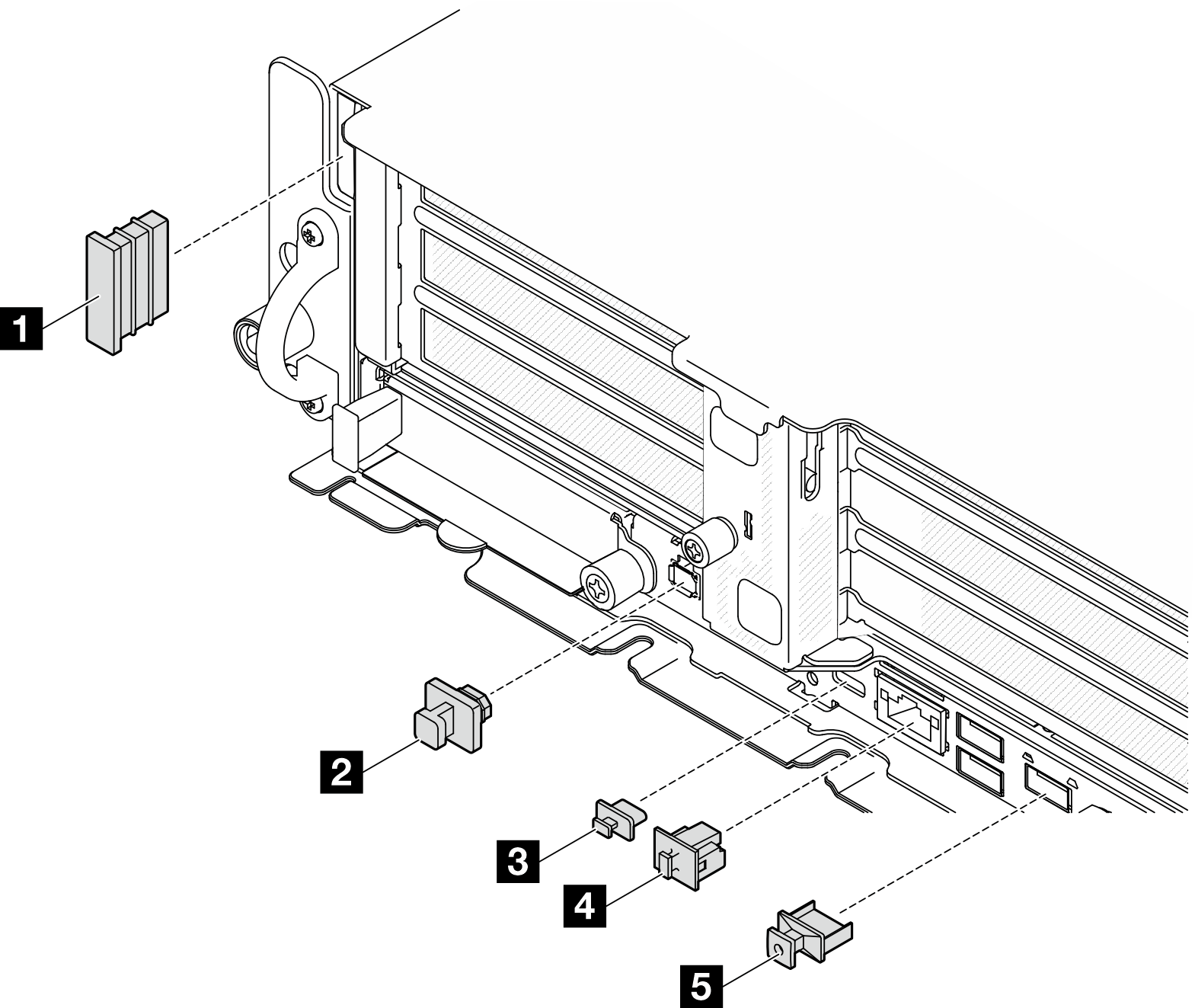
| 1 Security bezel slot filler (x2) | 4 RJ-45 filler (x1) |
| 2 External diagnostic handset connector filler (x1) | 5 USB Type-A filler (x3) |
| 3 USB Type-C filler (x1) |