Install the system board
Use this information to install the system board.
About this task
Removing and installing this component requires trained technicians. Do no attempt to remove or install it without proper training.
- Read the following section(s) to ensure that you work safely.
Touch the static-protective package that contains the component to any unpainted metal surface on the server; then, remove it from the package and place it on a static-protective surface.
Procedure
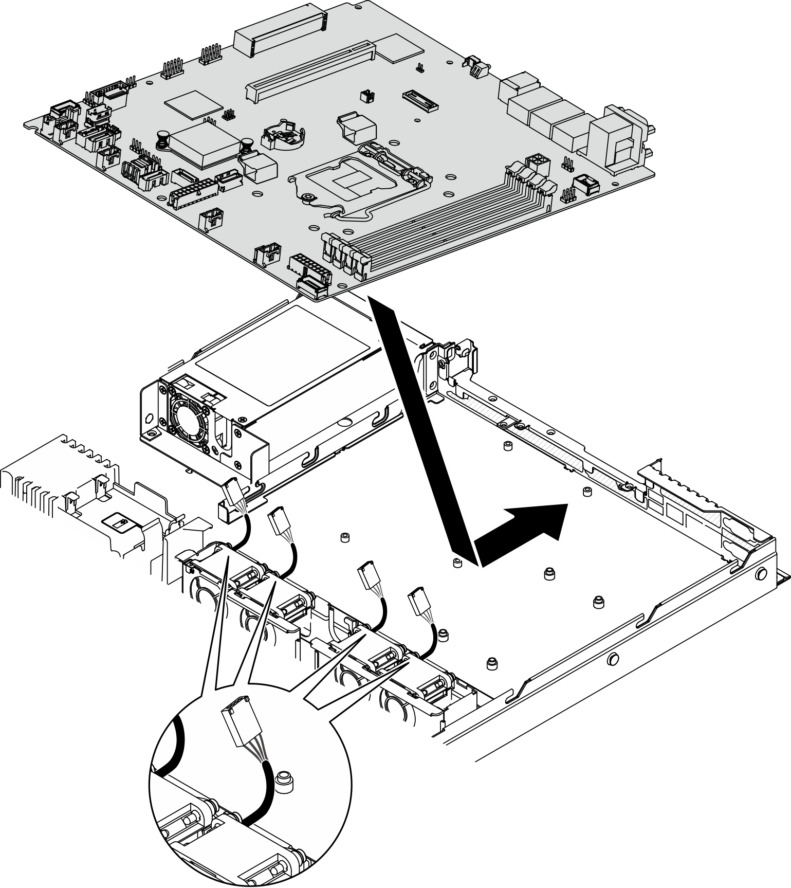
- Align the system board with serial and VGA ports on the rear side of the chassis. Carefully lower the system board into the chassis.
- Place the system board flat into the chassis. Match screw slots on the system board to the corresponding slots on the chassis.Figure 1. System board installation
- Place the system board flat into the chassis. Match screw slots on the system board to the corresponding slots on the chassis.
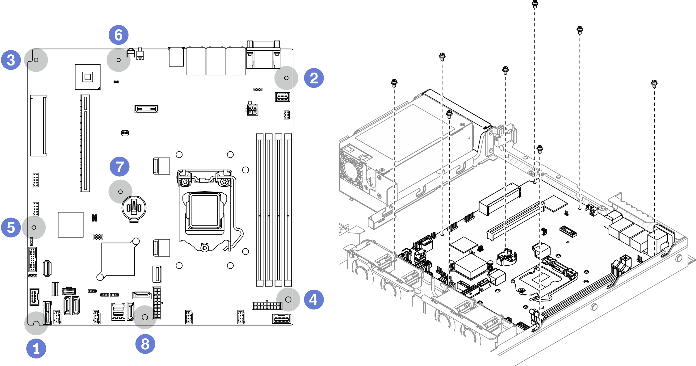
- Install all eight screws to secure the system board to the chassis according to the installation orders as shown.Figure 2. System-board screws location
 Note
Note- The order and locations of screws installation :
1 the lower left side 5 near front USB 3.0 / 2.0 header 2 the upper right side 6 near NMI button 3 the upper left side 7 near the CMOS battery 4 the lower right side 8 between the SATA connectors and the system power connector For reference, the torque which is required for the screws to be fully tightened or removed is 5.0 +/- 0.5 lb-in.
After you finish
Install the processor. See Install the processor.
Install the heat sink. See Install the heat sink.
Install the memory modules. See Install a memory module.
Connect the front operator panel cables to the system board. See Front panel cable routing.
Connect the fan cables to the system board by pressing it down until it clicks. See Fan cable routing.
Connect the M.2 boot adapter cables to the system board. See M.2 boot adapter cable routing.
Connect the backplate or the backplane cables to the system board. See Backplane and backplate cable routing.
Install the PCIe riser assembly. See Install the PCIe riser assembly.
Install the PCIe adapter to PCIe slot 3. See Install the PCIe adapter (Slot 3).
Install the air baffle. See Install the air baffle.
Install the top cover. See Install the top cover.
Complete the parts replacement. See Complete the parts replacement.
Reconnect power cords and all external cables.
Update the machine type and serial number with new vital product data (VPD). Use the Lenovo XClarity Provisioning Manager to update the machine type and serial number. See Update the machine type and serial number.
Enable TPM. See Enable TPM.
Optionally, enable UEFI Secure Boot. See Enable UEFI Secure Boot.
Demo video