Remove the system board
Use this information to remove the system board.
About this task
Removing and installing this component requires trained technicians. Do no attempt to remove or install it without proper training.
- Read the following section(s) to ensure that you work safely.
Record all system configuration information, such as Lenovo XClarity Controller IP addresses, vital product data, and the machine type, model number, serial number, Universally Unique Identifier, and asset tag of the server.
Use the Lenovo XClarity Essentials OneCLI to save the system configuration to external media.
Save the system-event log to external media.
When replacing the system board, always update the server with the latest firmware or restore the pre-existing firmware. Make sure that you have the latest firmware or a copy of the pre-existing firmware before you proceed.
Turn off the server. Disconnect the power cords and all external cables. See Power off the server.
If the server is installed in a rack, remove the server from the rack.
Procedure
- Remove all eight screws that secure the system board to the chassis.Figure 1. System-board screws location
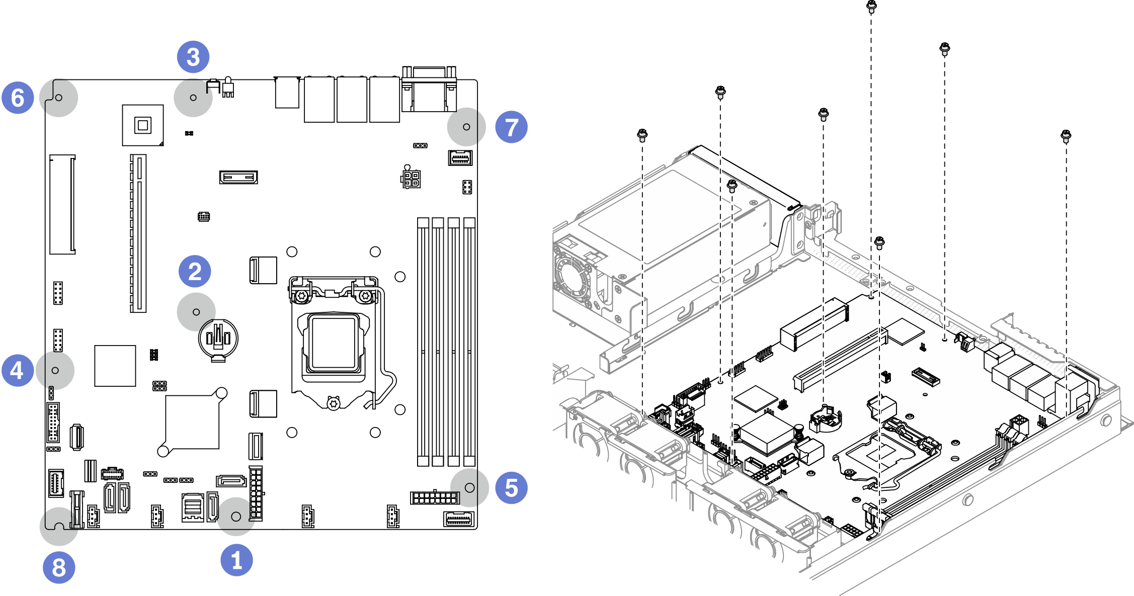 Note
Note- The order and locations of screws removal:
1 between the SATA connectors and the system power connector 5 the lower right side 2 near the CMOS battery 6 the upper left side 3 near NMI button 7 the upper right side 4 near front USB 3.0 / 2.0 header 8 the lower left side For reference, the torque which is required for the screws to be fully tightened or removed is 5.0 +/- 0.5 lb-in.
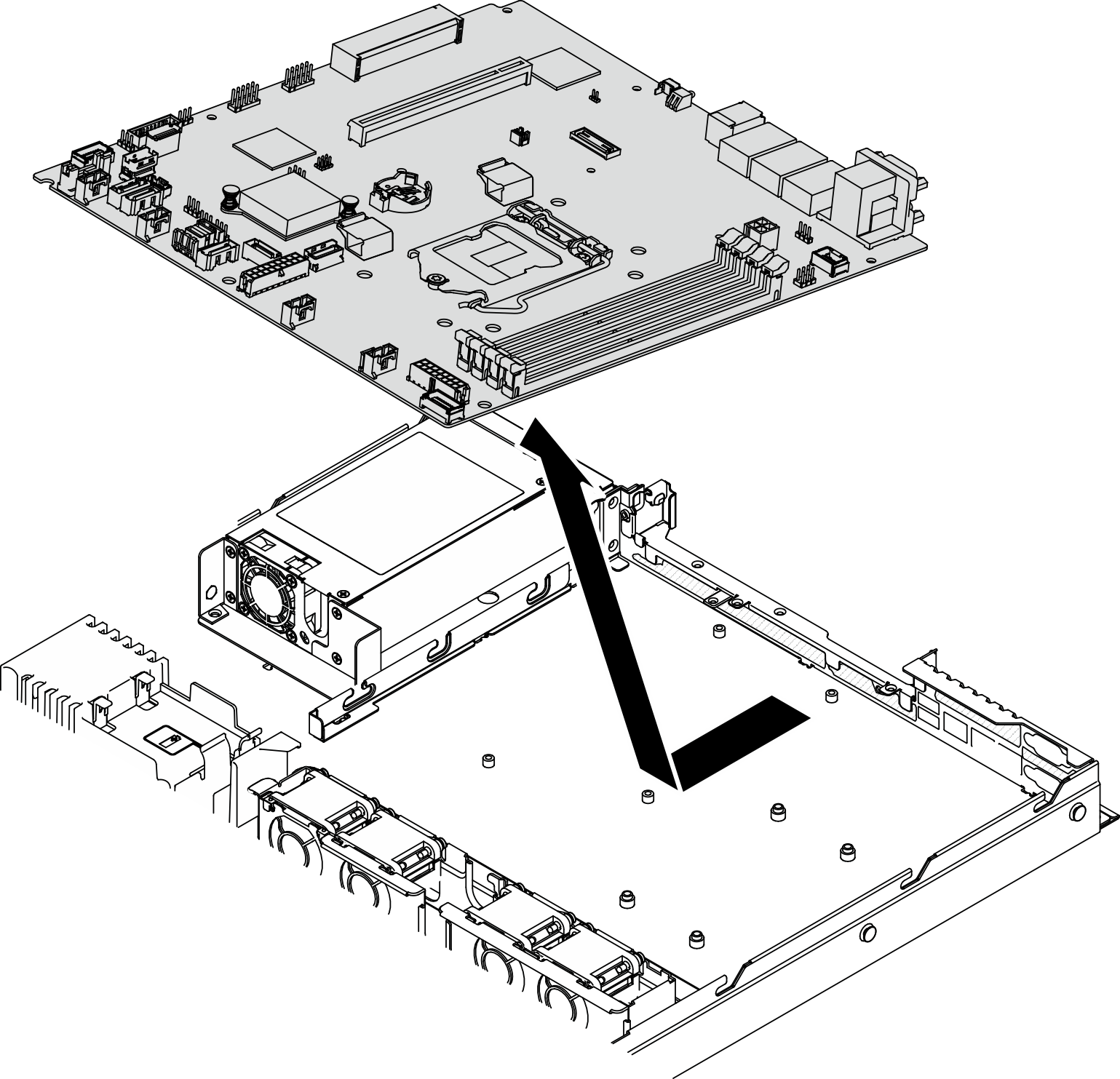
- Slightly lift up the front side of the system board; then, slide the system board towards the front of the server and lift it out of the server.Figure 2. System board removal
After you finish
Insert the new system board into the chassis. See Install the system board.
Take a socket cover from the processor socket assembly on the new system board and orient it correctly above the processor socket assembly on the removed system board.
Gently press down the socket cover legs to the processor socket assembly, pressing on the edges to avoid damage to the socket pins. You might hear a click on the socket cover is securely attached.
Make sure that the socket cover is securely attached to the processor socket assembly.
If you are instructed to return the component or optional device, follow all packaging instructions, and use any packaging materials for shipping that are supplied to you.
Demo video