Lenovo Compute Complex Neptune Core Module の取り外し
Compute Complex Neptune Core Module を取り外すには、このセクションの手順に従ってください。
重要
このタスクの実行は、Lenovo Service によって認定済みのトレーニングを受けた技術員が行う必要があります。適切なトレーニングおよび認定を受けずに取り外しまたは取り付けを行わないでください。
部品を初めて取り付ける場合は、Lenovo Professional Services・チームに連絡してサポートを受けてください。
このタスクについて
漏水検知センサー・モジュール・ケーブルの安全情報
S011

注意
鋭利な端、角、またはジョイントが近くにあります。
重要
安全に作業を行うために、取り付けのガイドラインおよび 安全検査のチェックリストをお読みください。
サーバーと周辺機器の電源をオフにし、電源コードとすべての外部ケーブルを取り外します。サーバーの電源をオフにするを参照してください。
静電気の影響を受けやすい部品は、静電気にさらされないように、取り付け時まで帯電防止パッケージに入れて保管してください。静電気放電用リスト・ストラップなどの接地システムを使用して部品を取り扱ってください。部品は帯電防止板に置いてください。
対応するねじを正しく取り付け、および取り外しできるよう、以下のドライバーを準備してください。
| トルク・ドライバー・タイプ・リスト | ねじタイプ |
|---|---|
| Torx T30 プラス・ドライバー | Torx T30 ねじ |
| #2 プラス・ドライバー | #2 プラスねじ |
手順
- ホース・ホルダー・カバーを開きます。図 1. ホルダー・カバーを開く
 カバーのつまみねじを緩めます。
 カバーを開きます。
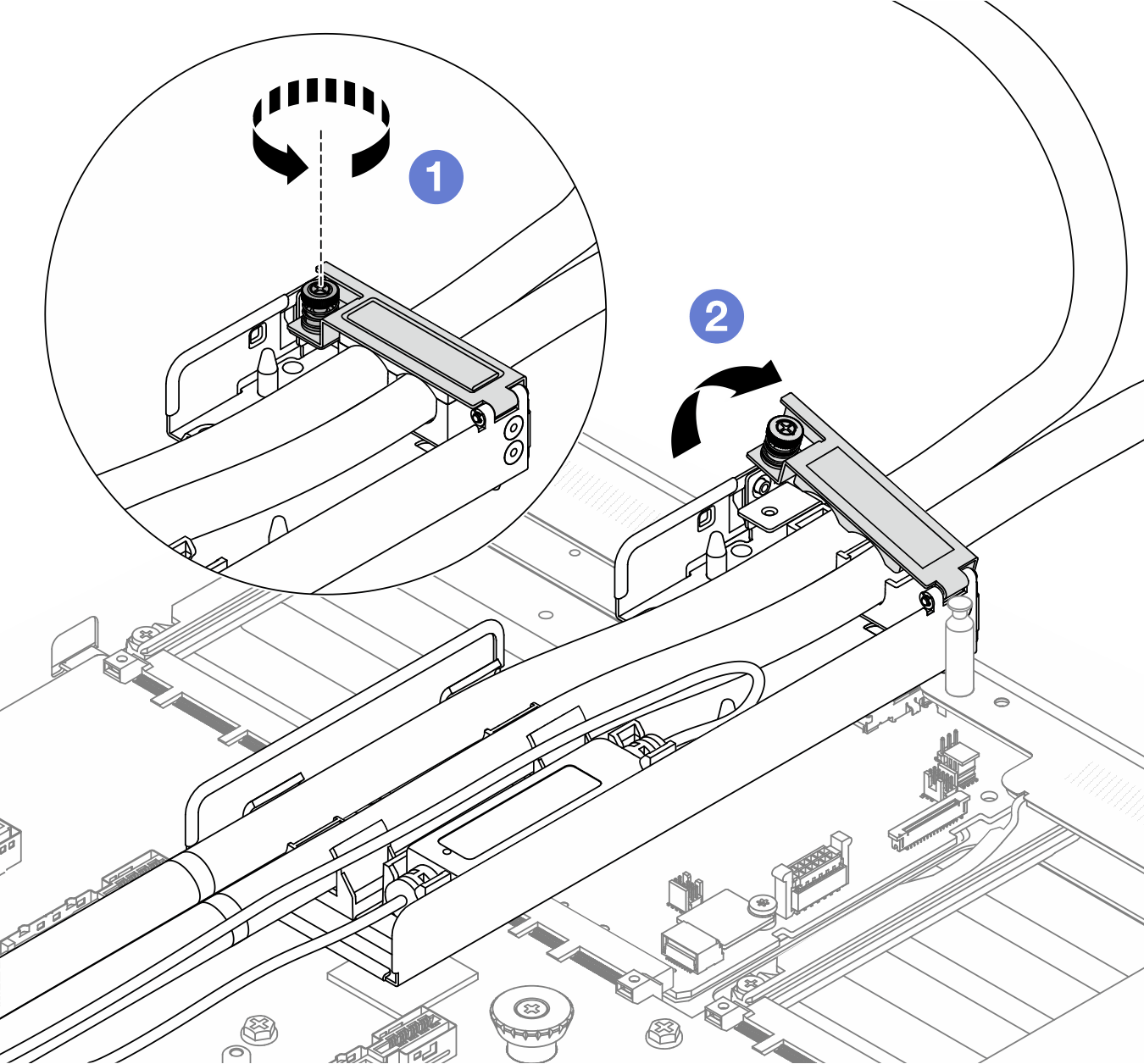
- ホースおよび漏水検知センサー・モジュールを取り外します。図 2. ホースとモジュールの取り外し
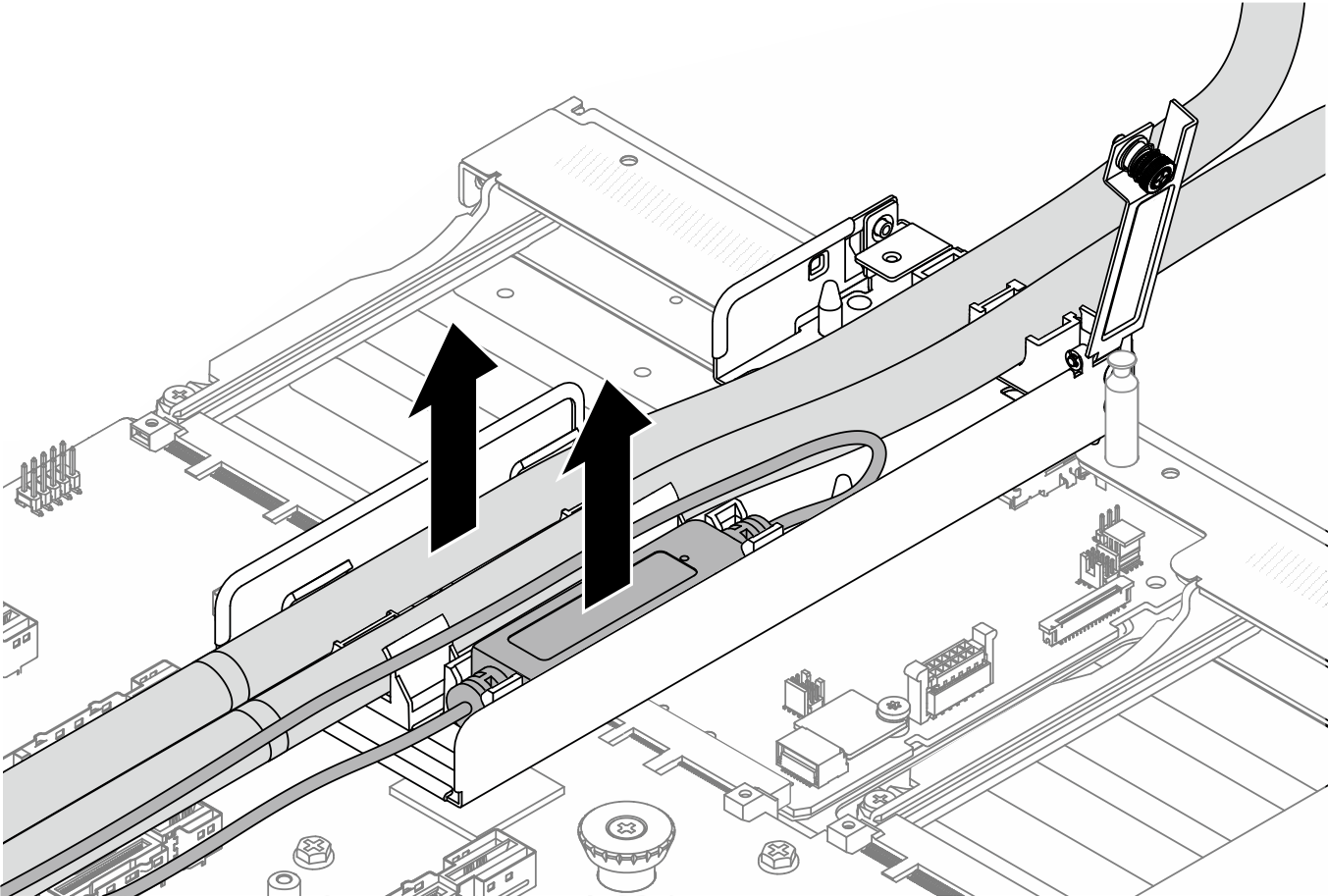
- ホルダー・ラッチを両側に押してモジュールのロックを解除します。
- ホースおよびモジュールを、ホース・ホルダーから外します。
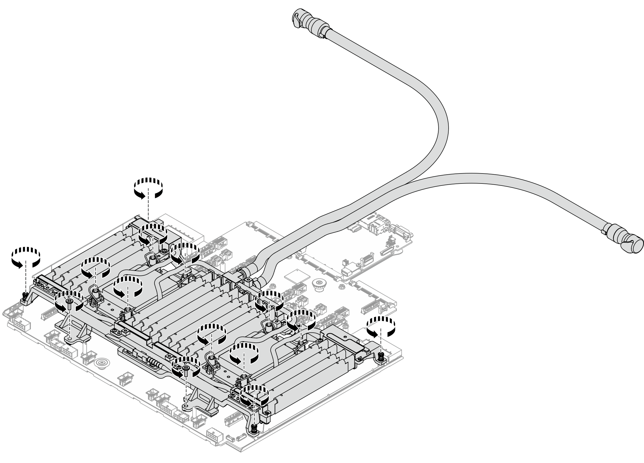
- Compute Complex Neptune Core Module 上の 6 本のねじと 8 個の Torx T30 ナットを緩めます。図 3. ねじを緩める
- モジュールに配送用トレイを取り付けます。図 4. 配送用トレイの取り付け
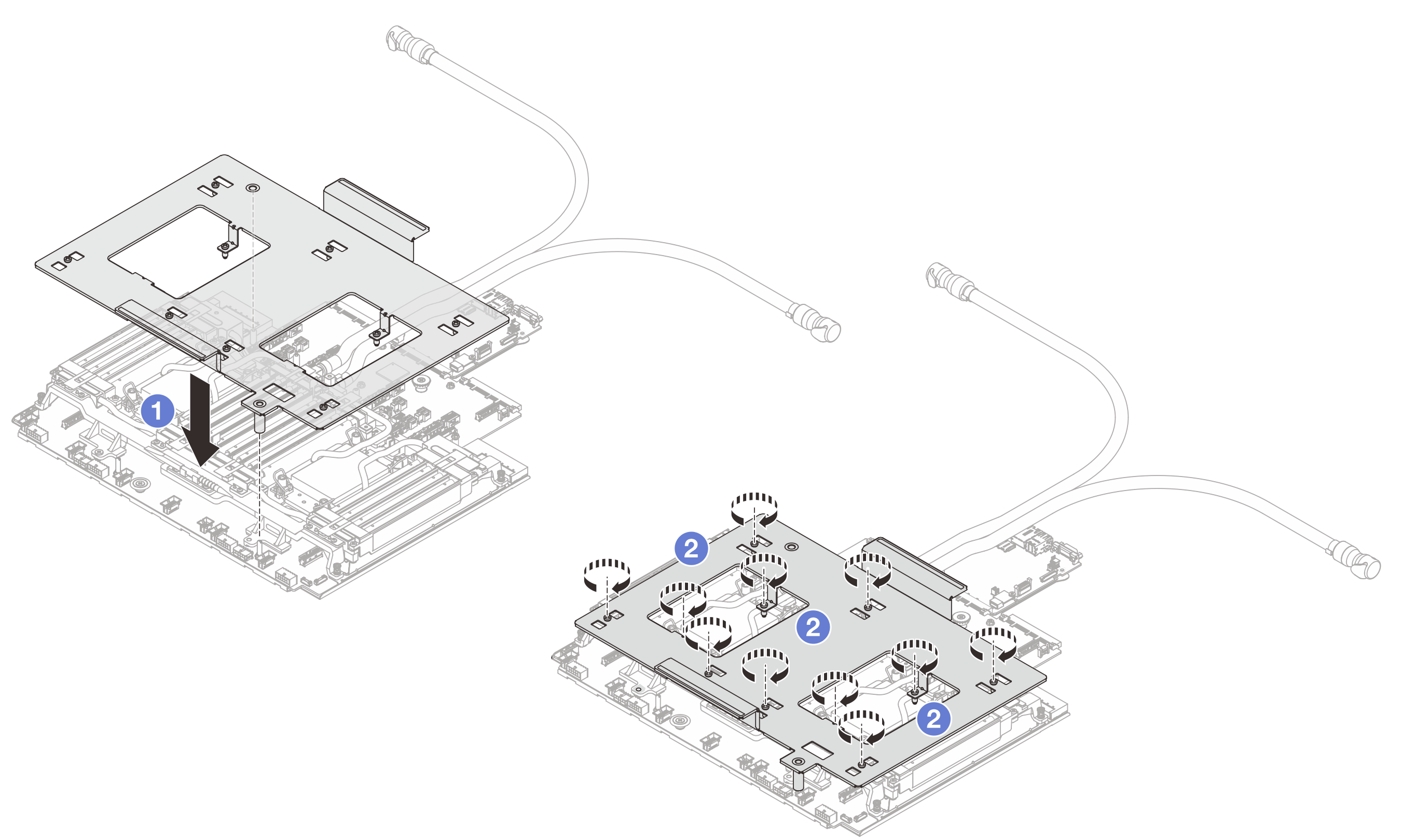
- モジュールに配送用トレイを取り付けます。
- ねじを締めて配送用トレイをロックします。
- プロセッサー・ボードからモジュールを外します。図 5. モジュールの取り外し
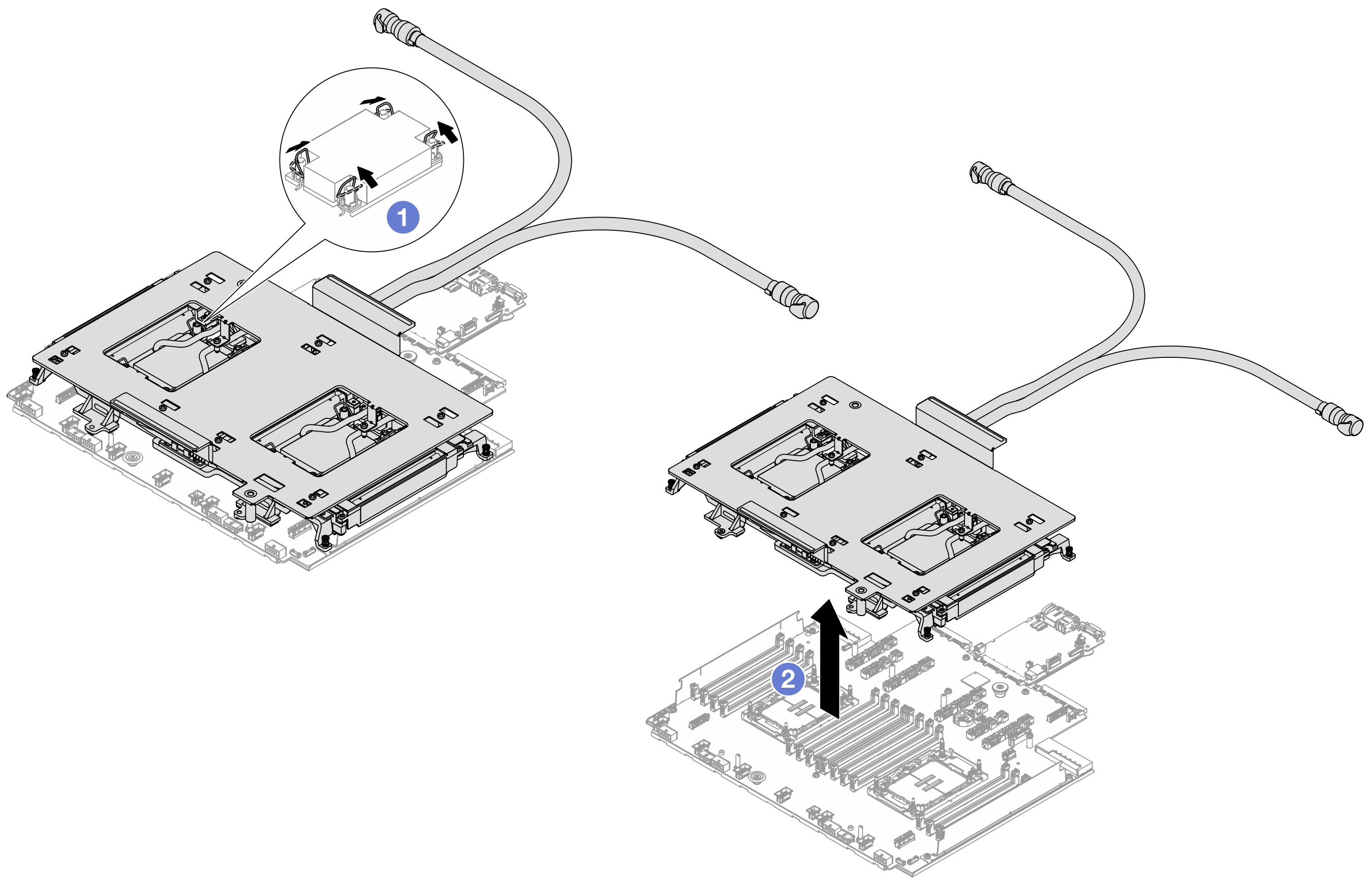
- 反傾斜ワイヤー・ベイルを内側に回転させます。
- を使って、プロセッサー・ソケットからモジュールをゆっくり持ち上げます。モジュールをソケットから完全に持ち上げられない場合は、Torx T30 ナットをさらに緩めて、再度モジュールを持ち上げてください。
- ホース・ホルダーを取り外します。図 6. ホルダーの取り外し
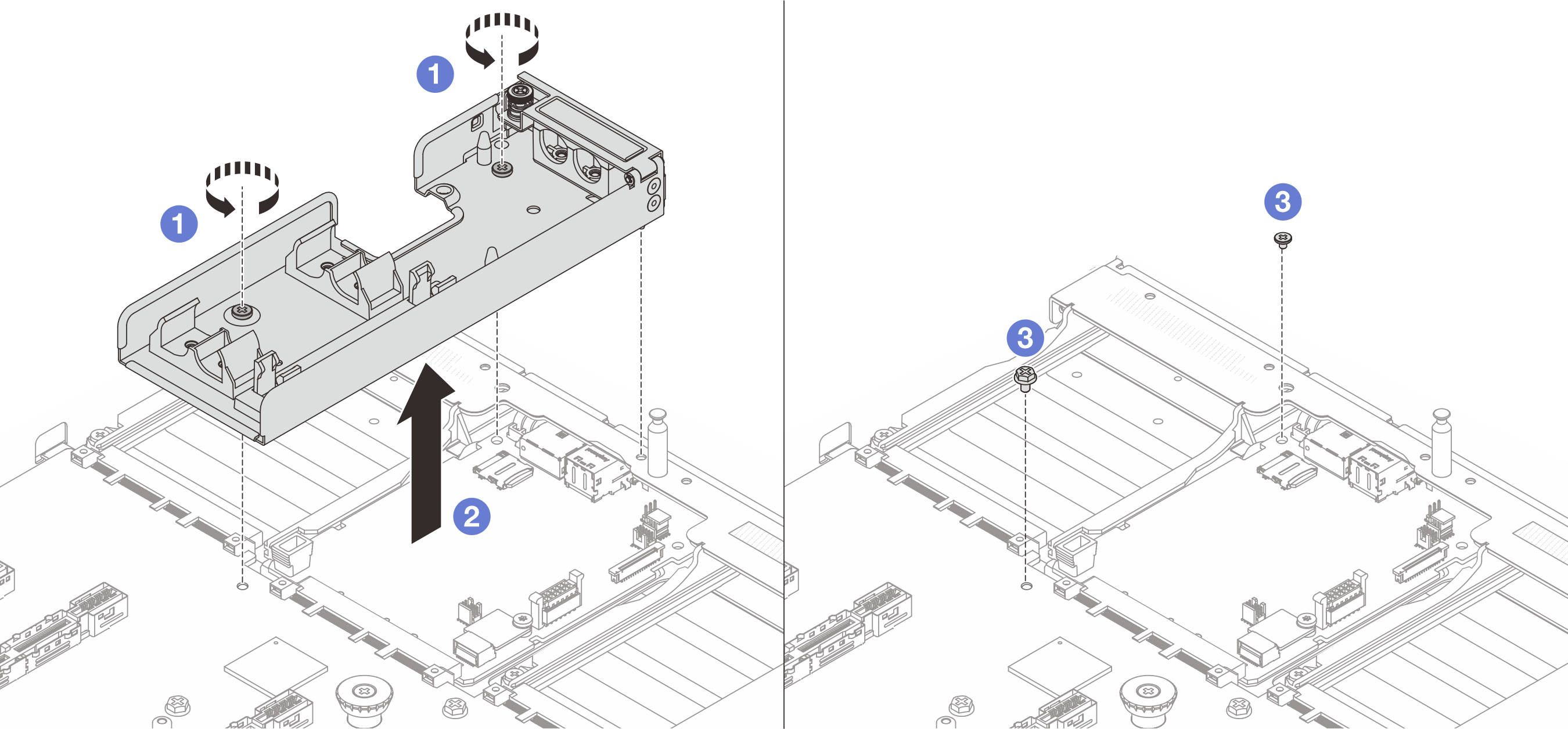
- ホルダーをシステム I/O ボードとプロセッサー・ボードに固定しているねじを緩めます。
- ホルダーを持ち上げて、シャーシから取り外します。
 システム I/O ボードとプロセッサー・ボードにねじを再度取り付けます。
完了したら
コンポーネントまたはオプション装置を返却するよう指示された場合は、すべての梱包上の指示に従い、提供された配送用の梱包材がある場合はそれを使用してください。
デモ・ビデオ
フィードバックを送る