Modelli di server con dieci unità NVMe da 2,5 pollici
Utilizzare questa sezione per conoscere i connettori sul backplane e comprendere l'instradamento dei cavi interni per i modelli di server con dieci unità NVMe da 2,5 pollici.
Figura 1. Connettori sul backplane per dieci unità NVMe da 2,5 pollici
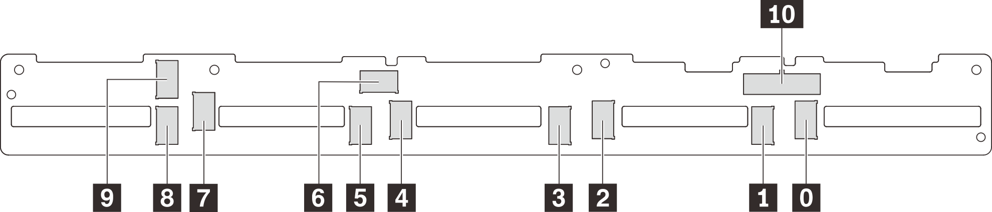
| 0 Connettore NVMe 0 | 1 Connettore NVMe 1 | 2 Connettore NVMe 2 | 3 Connettore NVMe 3 |
| 4 Connettore NVMe 4 | 5 Connettore NVMe 5 | 6 Connettore NVMe 6 | 7 Connettore NVMe 7 |
| 8 Connettore NVMe 8 | 9 Connettore NVMe 9 | 10 Connettore di alimentazione |
Modelli di server con dieci unità NVMe da 2,5 pollici, un adattatore dello switch NVMe 1610-4P nello slot PCIe 2 e un adattatore dello switch NVMe 1610-4P nello slot PCIe 3
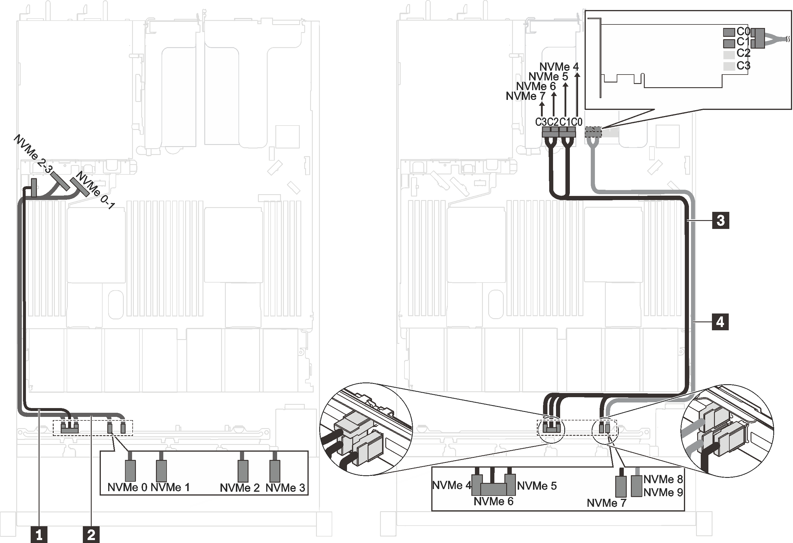
Figura 2. Instradamento dei cavi per i modelli di server con dieci unità NVMe da 2,5 pollici, un adattatore dello switch NVMe 1610-4P nello slot PCIe 2 e un adattatore dello switch NVMe 1610-4P nello slot PCIe 3
| Cavo | Da | A |
|---|---|---|
| 1 Cavo di alimentazione per il backplane anteriore | Connettore di alimentazione sul backplane anteriore | Connettore di alimentazione del backplane anteriore sulla scheda di sistema |
| 2 Cavo di segnale NVMe per il backplane anteriore | Connettori NVMe 0, NVMe 1, NVMe 2 e NVMe 3 sul backplane anteriore | Connettore NVMe 0-1 e connettore NVMe 2-3 sulla scheda di sistema |
| 3 Cavo di segnale NVMe per il backplane anteriore | Connettori NVMe 4, NVMe 5, NVMe 6 e NVMe 7 sul backplane anteriore | Connettori C0, C1, C2 e C3 sull'adattatore dello switch NVMe installato nello slot PCIe 3 |
| 4 Cavo di segnale NVMe per il backplane anteriore | Connettori NVMe 8 e NVMe 9 sul backplane anteriore | Connettori C0 e C1 sull'adattatore dello switch NVMe installato nello slot PCIe 2 |
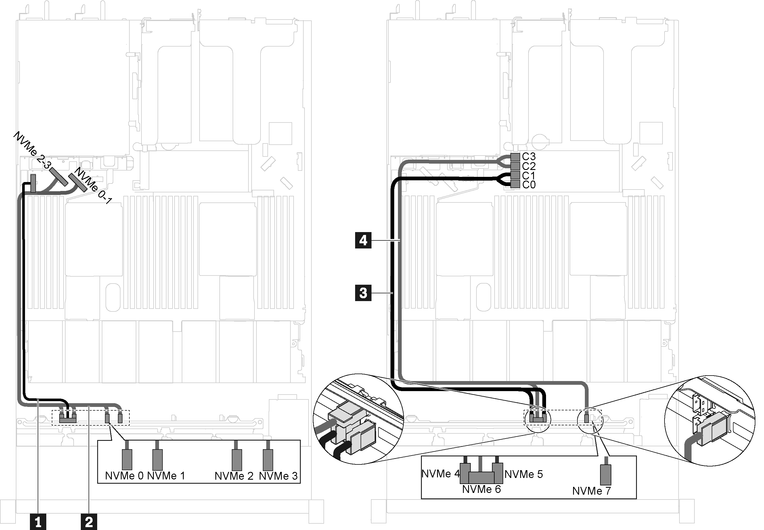
Modelli di server con dieci unità NVMe da 2,5 pollici, un adattatore dello switch NVMe 1610-4P nello slot PCIe 2 e un adattatore dello switch NVMe 810-4P nello slot dell'adattatore RAID
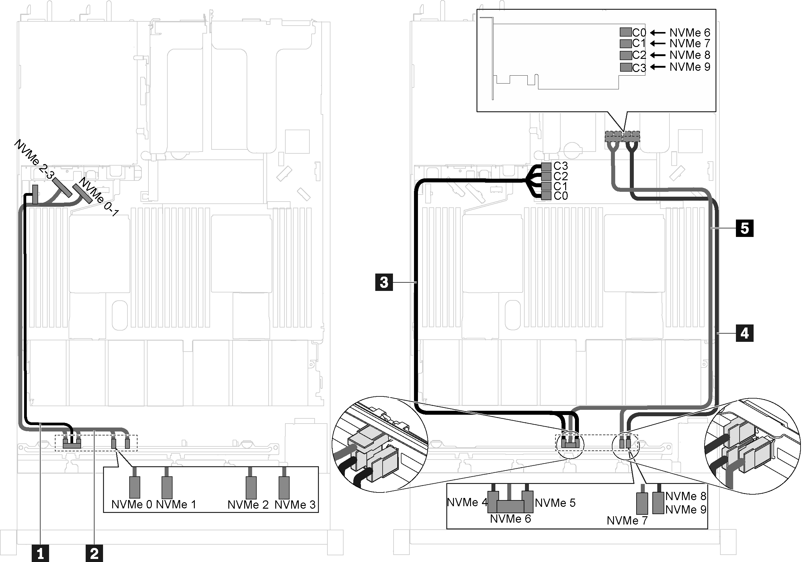
Figura 3. Instradamento dei cavi per i modelli di server con dieci unità NVMe da 2,5 pollici, un adattatore dello switch NVMe 1610-4P nello slot PCIe 2 e un adattatore dello switch NVMe 810-4P nello slot dell'adattatore RAID
| Cavo | Da | A |
|---|---|---|
| 1 Cavo di alimentazione per il backplane anteriore | Connettore di alimentazione sul backplane anteriore | Connettore di alimentazione del backplane anteriore sulla scheda di sistema |
| 2 Cavo di segnale NVMe per il backplane anteriore | Connettori NVMe 0, NVMe 1, NVMe 2 e NVMe 3 sul backplane anteriore | Connettore NVMe 0-1 e connettore NVMe 2-3 sulla scheda di sistema |
| 3 Cavo di segnale NVMe per il backplane anteriore | Connettori NVMe 4 e NVMe 5 sul backplane anteriore | Connettori C0, C1, C2 e C3 sull'adattatore dello switch NVMe installato nello slot dell'adattatore RAID |
| 4 Cavo di segnale NVMe per il backplane anteriore | Connettori NVMe 6 e NVMe 7 sul backplane anteriore | Connettori C0 e C1 sull'adattatore dello switch NVMe installato nello slot PCIe 2 |
| 5 Cavo di segnale NVMe per il backplane anteriore | Connettori NVMe 8 e NVMe 9 sul backplane anteriore | Connettori C2 e C3 sull'adattatore dello switch NVMe installato nello slot PCIe 2 |
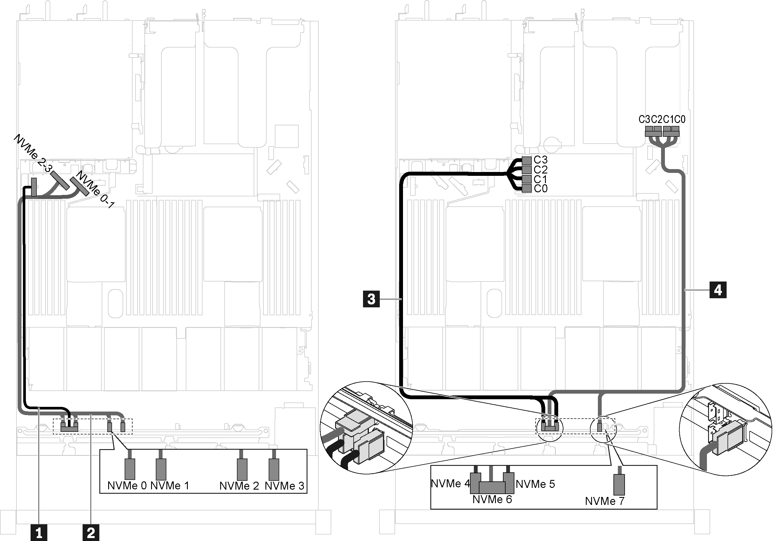
Modello di server con dieci unità NVMe da 2,5 pollici e un adattatore switch NVMe 1611-8P nello slot PCIe 2
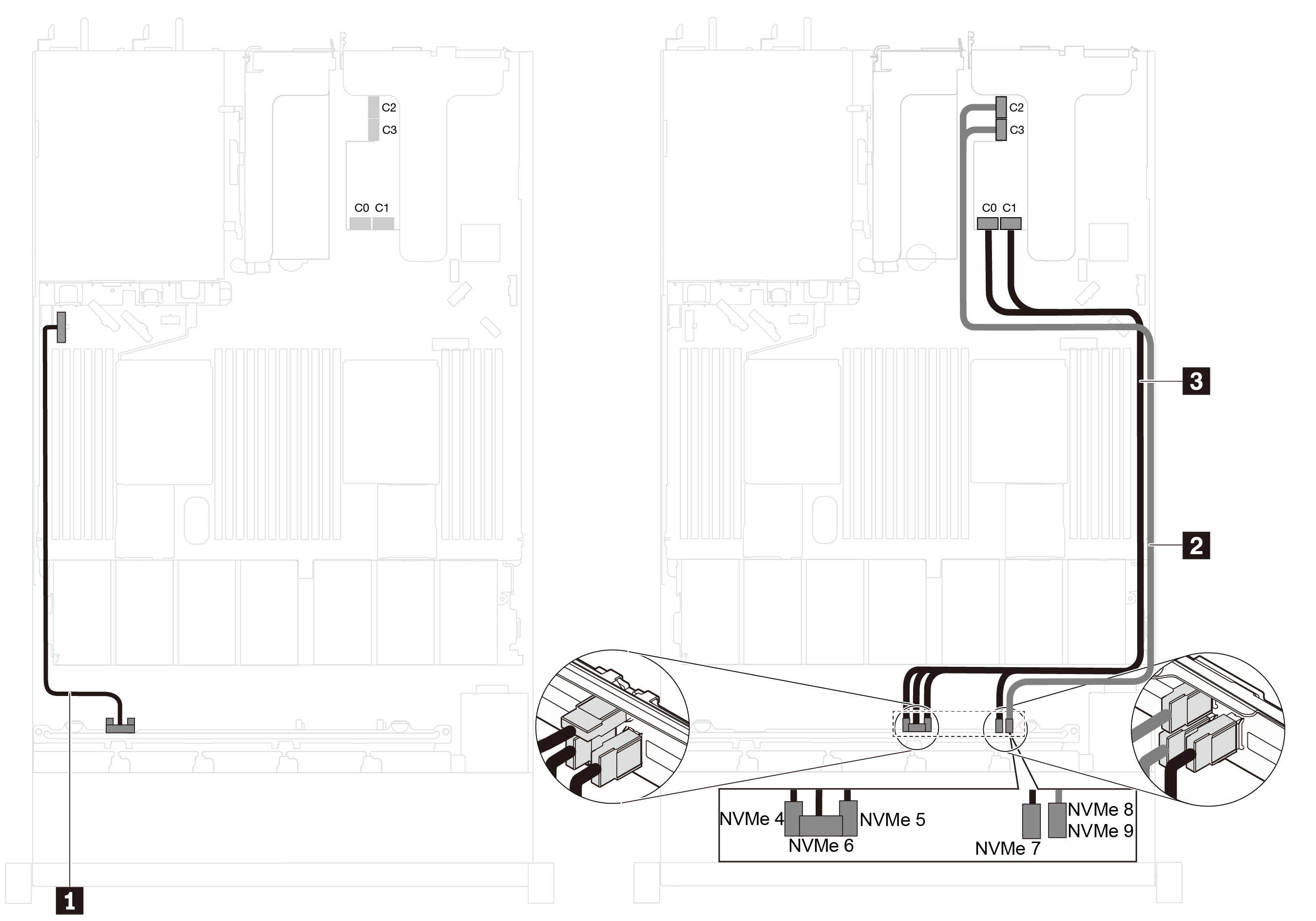
Figura 4. Instradamento dei cavi per i modelli di server con dieci unità NVMe da 2,5 pollici e un adattatore dello switch NVMe 1611-8P nello slot PCIe 2
| Cavo | Da | A |
|---|---|---|
| 1 Cavo di alimentazione per il backplane anteriore | Connettore di alimentazione sul backplane anteriore | Connettore di alimentazione del backplane anteriore sulla scheda di sistema |
| 2 Cavo di segnale NVMe per il backplane anteriore | Connettori NVMe 8 e NVMe 9 sul backplane anteriore | Connettori C2 e C3 sull'adattatore dello switch NVMe installato nello slot PCIe 2 |
| 3 Cavo di segnale NVMe per il backplane anteriore | Connettori NVMe 4, NVMe 5, NVMe 6 e NVMe 7 sul backplane anteriore | Connettori C0 e C1 sull'adattatore dello switch NVMe installato nello slot PCIe 2 |
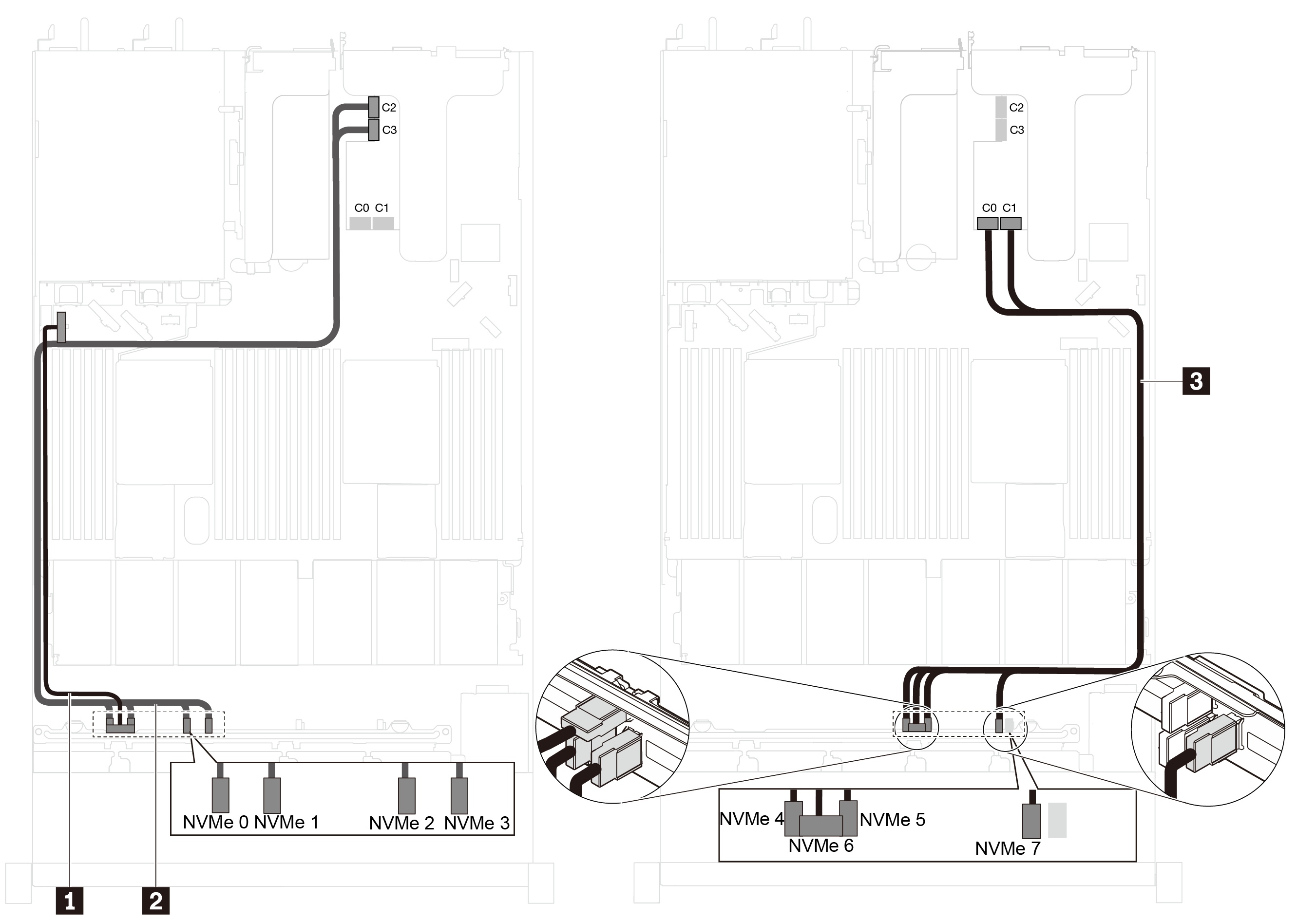
Modelli di server con otto unità NVMe da 2,5 pollici e un adattatore dello switch NVMe 810-4P nello slot dell'adattatore RAID
Figura 5. Instradamento dei cavi per i modelli di server con otto unità NVMe da 2,5 pollici e un adattatore dello switch NVMe 810-4P nello slot dell'adattatore RAID
| Cavo | Da | A |
|---|---|---|
| 1 Cavo di alimentazione per il backplane anteriore | Connettore di alimentazione sul backplane anteriore | Connettore di alimentazione del backplane anteriore sulla scheda di sistema |
| 2 Cavo di segnale NVMe per il backplane anteriore | Connettori NVMe 0, NVMe 1, NVMe 2 e NVMe 3 sul backplane anteriore | Connettore NVMe 0-1 e connettore NVMe 2-3 sulla scheda di sistema |
| 3 Cavo di segnale NVMe per il backplane anteriore | Connettori NVMe 4 e NVMe 5 sul backplane anteriore | Connettori C0 e C1 sull'adattatore dello switch NVMe installato nello slot dell'adattatore RAID |
| 4 Cavo di segnale NVMe per il backplane anteriore | Connettori NVMe 6 e NVMe 7 sul backplane anteriore | Connettori C2 e C3 sull'adattatore dello switch NVMe installato nello slot dell'adattatore RAID |
Modelli di server con otto unità NVMe da 2,5 pollici, un adattatore dello switch NVMe 810-4P nello slot PCIe 1 e un adattatore dello switch NVMe 810-4P nello slot dell'adattatore RAID
Figura 6. Instradamento dei cavi per i modelli di server con otto unità NVMe da 2,5 pollici, un adattatore dello switch NVMe 810-4P nello slot PCIe 1 e un adattatore dello switch NVMe 810-4P nello slot dell'adattatore RAID
| Cavo | Da | A |
|---|---|---|
| 1 Cavo di alimentazione per il backplane anteriore | Connettore di alimentazione sul backplane anteriore | Connettore di alimentazione del backplane anteriore sulla scheda di sistema |
| 2 Cavo di segnale NVMe per il backplane anteriore | Connettori NVMe 0, NVMe 1, NVMe 2 e NVMe 3 sul backplane anteriore | Connettore NVMe 0-1 e connettore NVMe 2-3 sulla scheda di sistema |
| 3 Cavo di segnale NVMe per il backplane anteriore | Connettori NVMe 4 e NVMe 5 sul backplane anteriore | Connettori C0, C1, C2 e C3 sull'adattatore dello switch NVMe installato nello slot dell'adattatore RAID |
| 4 Cavo di segnale NVMe per il backplane anteriore | Connettori NVMe 6 e NVMe 7 sul backplane anteriore | Connettori C0, C1, C2 e C3 sull'adattatore dello switch NVMe installato nello slot PCIe 1 |
Modelli di server con otto unità NVMe da 2,5 pollici e un adattatore switch NVMe 1611-8P nello slot PCIe 2
Figura 7. Instradamento dei cavi per i modelli di server con otto unità NVMe da 2,5 pollici e un adattatore dello switch NVMe 1611-8P nello slot PCIe 2
| Cavo | Da | A |
|---|---|---|
| 1 Cavo di alimentazione per il backplane anteriore | Connettore di alimentazione sul backplane anteriore | Connettore di alimentazione del backplane anteriore sulla scheda di sistema |
| 2 Cavo di segnale NVMe per il backplane anteriore | Connettori NVMe 0, NVMe 1, NVMe 2 e NVMe 3 sul backplane anteriore | Connettori C2 e C3 sull'adattatore dello switch NVMe installato nello slot PCIe 2 |
| 3 Cavo di segnale NVMe per il backplane anteriore | Connettori NVMe 4, NVMe 5, NVMe 6 e NVMe 7 sul backplane anteriore | Connettori C0 e C1 sull'adattatore dello switch NVMe installato nello slot PCIe 2 |
Envoyer des commentaires