Server models with ten 2.5-inch NVMe drives
Use this section to understand the connectors on the backplane and the internal cable routing for server models with ten 2.5-inch NVMe drives.
Figure 1. Connectors on the backplane for ten 2.5-inch NVMe drives
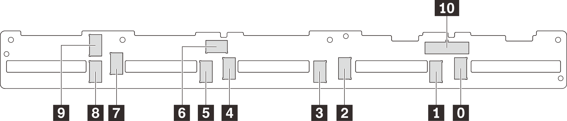
| 0 NVMe 0 connector | 1 NVMe 1 connector | 2 NVMe 2 connector | 3 NVMe 3 connector |
| 4 NVMe 4 connector | 5 NVMe 5 connector | 6 NVMe 6 connector | 7 NVMe 7 connector |
| 8 NVMe 8 connector | 9 NVMe 9 connector | 10 Power connector |
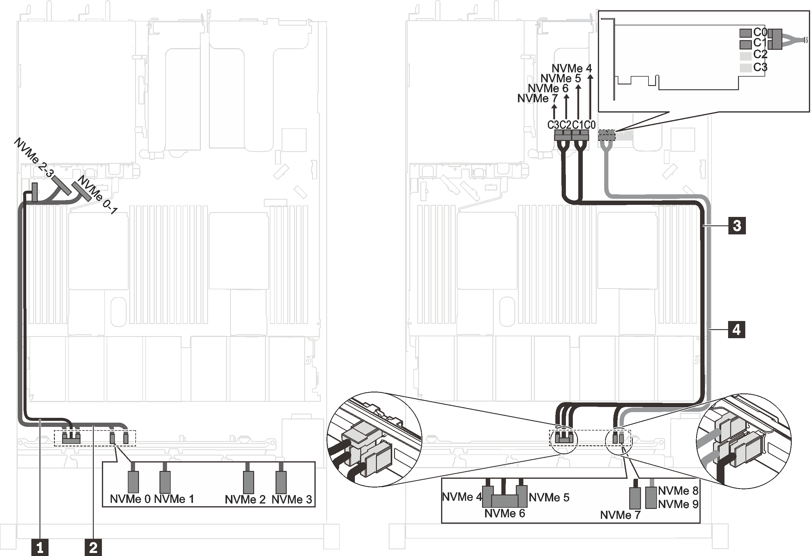
Server models with ten 2.5-inch NVMe drives, one 1610-4P NVMe switch adapter in PCIe slot 2, and one 1610-4P NVMe switch adapter in PCIe slot 3
Figure 2. Cable routing for server models with ten 2.5-inch NVMe drives, one 1610-4P NVMe switch adapter in PCIe slot 2, and one 1610-4P NVMe switch adapter in PCIe slot 3
| Cable | From | To |
|---|---|---|
| 1 Power cable for front backplane | Power connector on the front backplane | Front-backplane power connector on the system board |
| 2 NVMe signal cable for front backplane | NVMe 0, NVMe 1, NVMe 2, and NVMe 3 connectors on the front backplane | NVMe 0-1 connector and NVMe 2-3 connector on the system board |
| 3 NVMe signal cable for front backplane | NVMe 4, NVMe 5, NVMe 6, and NVMe 7 connectors on the front backplane | C0, C1, C2, and C3 connectors on the NVMe switch adapter installed in PCIe slot 3 |
| 4 NVMe signal cable for front backplane | NVMe 8 and NVMe 9 connectors on the front backplane | C0 and C1 connectors on the NVMe switch adapter installed in PCIe slot 2 |
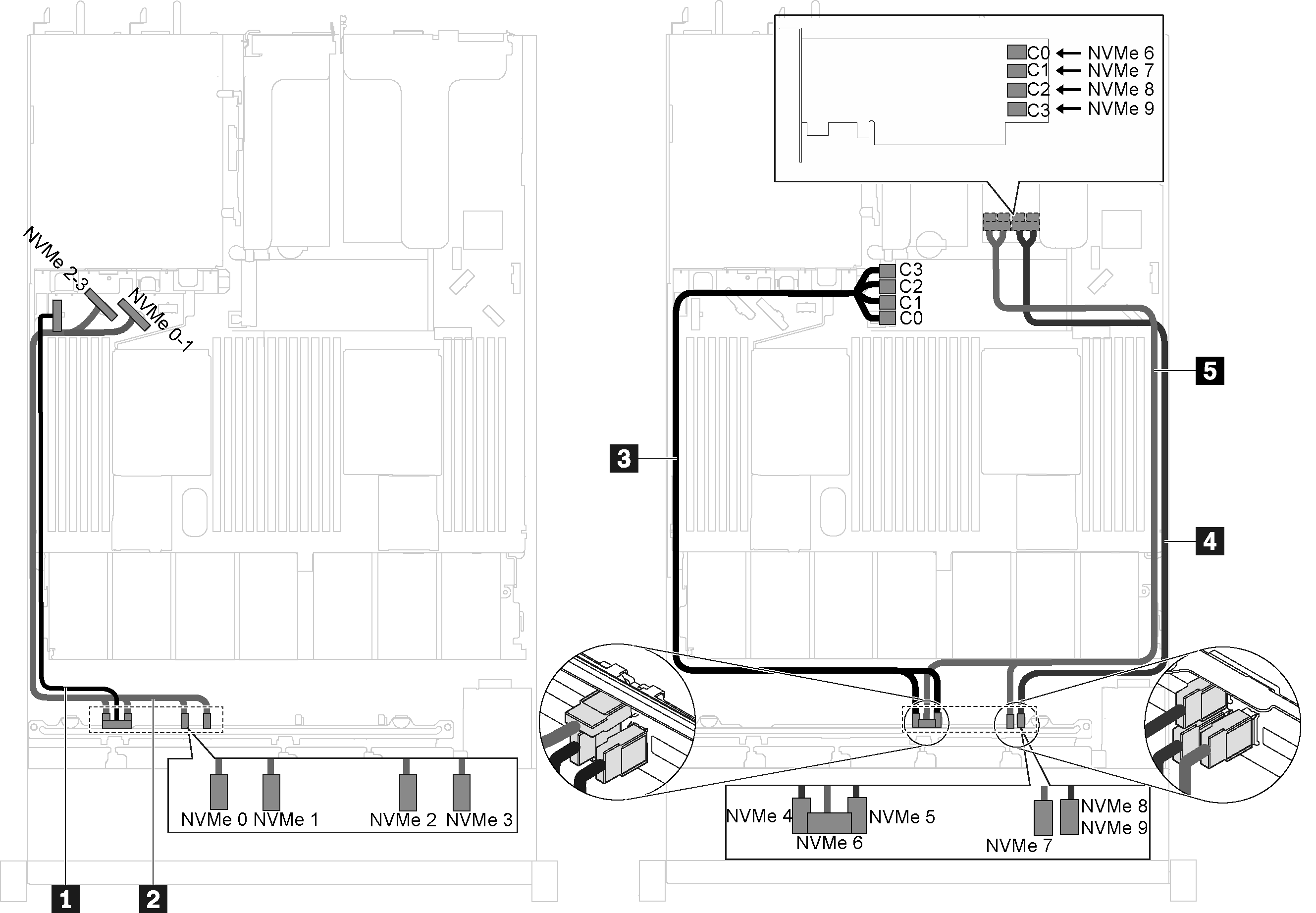
Server models with ten 2.5-inch NVMe drives, one 1610-4P NVMe switch adapter in PCIe slot 2, and one 810-4P NVMe switch adapter in the RAID adapter slot
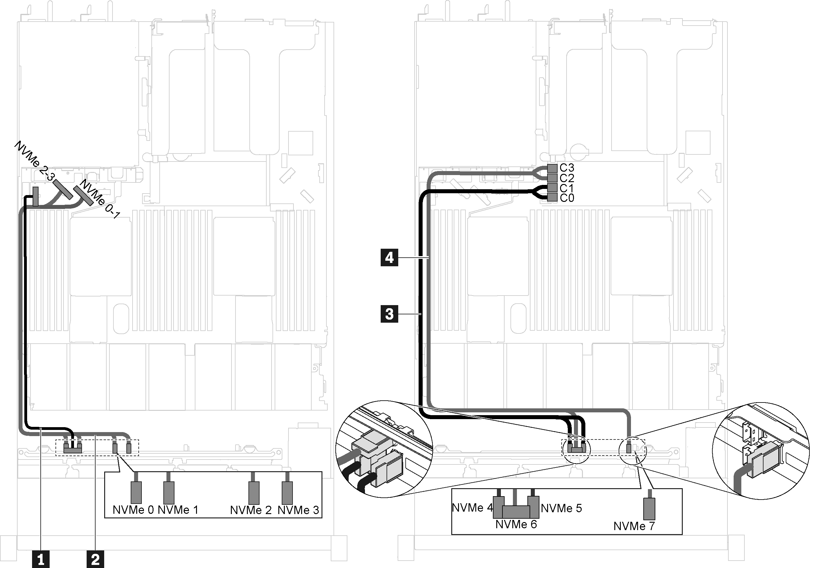
Figure 3. Cable routing for server models with ten 2.5-inch NVMe drives, one 1610-4P NVMe switch adapter in PCIe slot 2, and one 810-4P NVMe switch adapter in the RAID adapter slot
| Cable | From | To |
|---|---|---|
| 1 Power cable for front backplane | Power connector on the front backplane | Front-backplane power connector on the system board |
| 2 NVMe signal cable for front backplane | NVMe 0, NVMe 1, NVMe 2, and NVMe 3 connectors on the front backplane | NVMe 0-1 connector and NVMe 2-3 connector on the system board |
| 3 NVMe signal cable for front backplane | NVMe 4 and NVMe 5 connectors on the front backplane | C0, C1, C2, and C3 connectors on the NVMe switch adapter installed in the RAID adapter slot |
| 4 NVMe signal cable for front backplane | NVMe 6 and NVMe 7 connectors on the front backplane | C0 and C1 connectors on the NVMe switch adapter installed in PCIe slot 2 |
| 5 NVMe signal cable for front backplane | NVMe 8 and NVMe 9 connectors on the front backplane | C2 and C3 connectors on the NVMe switch adapter installed in PCIe slot 2 |
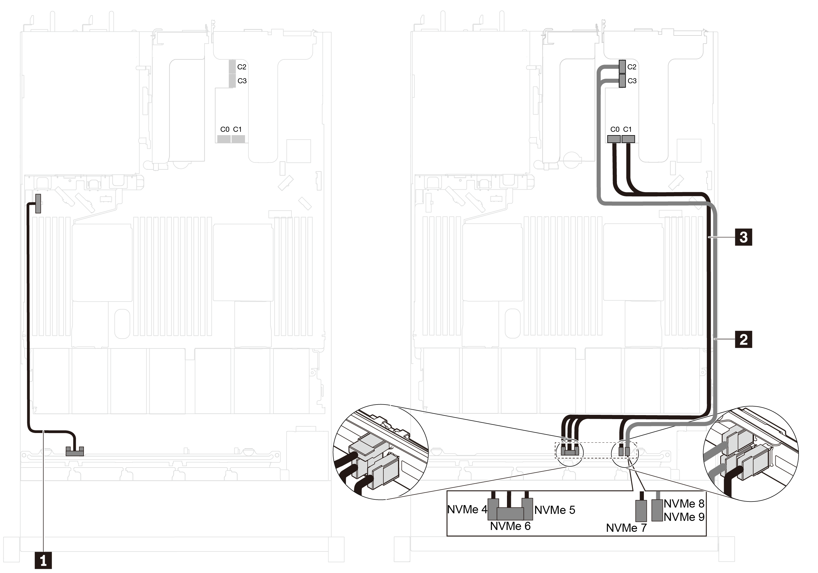
Server model with ten 2.5-inch NVMe drives and one NVMe 1611-8P switch adapter in PCIe slot 2
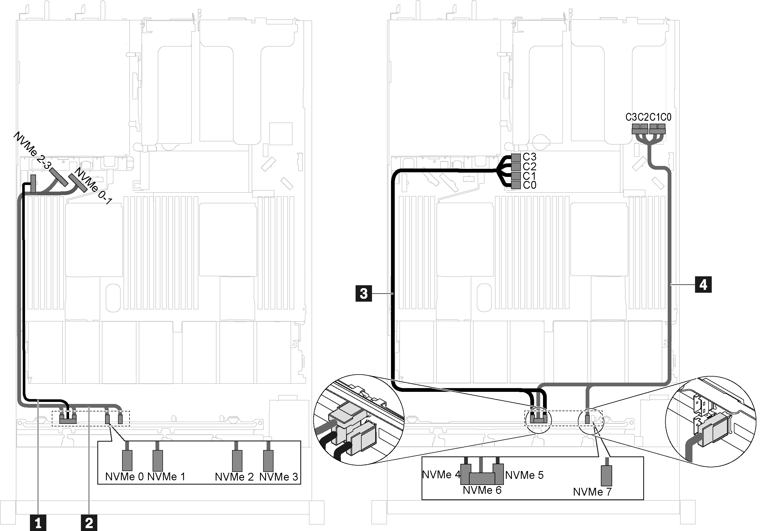
Figure 4. Cable routing for server models with ten 2.5-inch NVMe drives and one NVMe 1611-8P switch adapter in PCIe slot 2
| Cable | From | To |
|---|---|---|
| 1 Power cable for front backplane | Power connector on the front backplane | Front-backplane power connector on the system board |
| 2 NVMe signal cable for front backplane | NVMe 8 and NVMe 9 connectors on the front backplane | C2 and C3 connectors on the NVMe switch adapter installed in PCIe slot 2 |
| 3 NVMe signal cable for front backplane | NVMe 4, NVMe 5, NVMe 6, and NVMe 7 connectors on the front backplane | C0 and C1 connectors on the NVMe switch adapter installed in PCIe slot 2 |
Server models with eight 2.5-inch NVMe drives and one 810-4P NVMe switch adapter in the RAID adapter slot
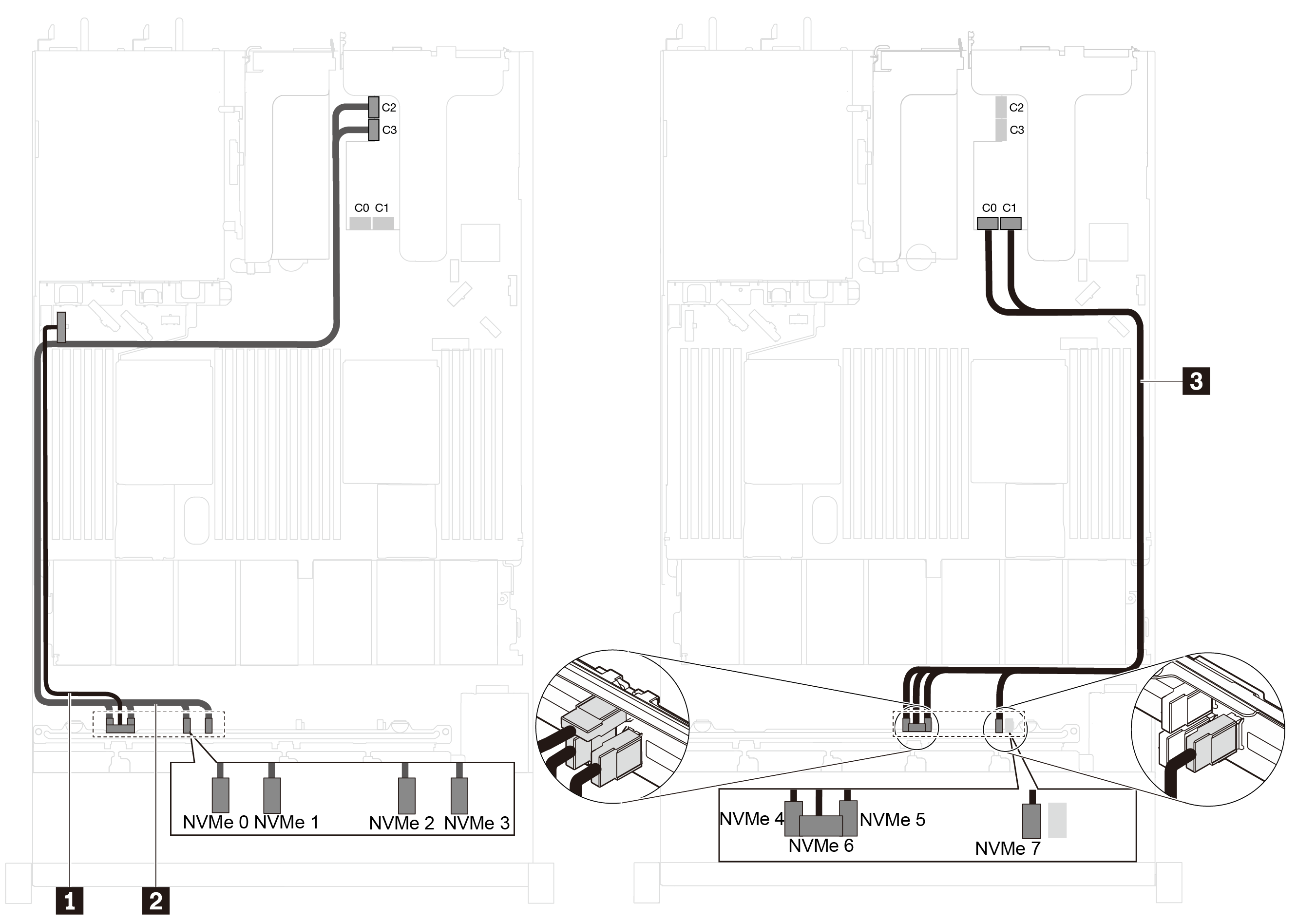
Figure 5. Cable routing for server models with eight 2.5-inch NVMe drives and one 810-4P NVMe switch adapter in the RAID adapter slot
| Cable | From | To |
|---|---|---|
| 1 Power cable for front backplane | Power connector on the front backplane | Front-backplane power connector on the system board |
| 2 NVMe signal cable for front backplane | NVMe 0, NVMe 1, NVMe 2, and NVMe 3 connectors on the front backplane | NVMe 0-1 connector and NVMe 2-3 connector on the system board |
| 3 NVMe signal cable for front backplane | NVMe 4 and NVMe 5 connectors on the front backplane | C0 and C1 connectors on the NVMe switch adapter installed in the RAID adapter slot |
| 4 NVMe signal cable for front backplane | NVMe 6 and NVMe 7 connectors on the front backplane | C2 and C3 connectors on the NVMe switch adapter installed in the RAID adapter slot |
Server models with eight 2.5-inch NVMe drives, one 810-4P NVMe switch adapter in PCIe slot 1, and one 810-4P NVMe switch adapter in the RAID adapter slot
Figure 6. Cable routing for server models with eight 2.5-inch NVMe drives, one 810-4P NVMe switch adapter in PCIe slot 1, and one 810-4P NVMe switch adapter in the RAID adapter slot
| Cable | From | To |
|---|---|---|
| 1 Power cable for front backplane | Power connector on the front backplane | Front-backplane power connector on the system board |
| 2 NVMe signal cable for front backplane | NVMe 0, NVMe 1, NVMe 2, and NVMe 3 connectors on the front backplane | NVMe 0-1 connector and NVMe 2-3 connector on the system board |
| 3 NVMe signal cable for front backplane | NVMe 4 and NVMe 5 connectors on the front backplane | C0, C1, C2, and C3 connectors on the NVMe switch adapter installed in the RAID adapter slot |
| 4 NVMe signal cable for front backplane | NVMe 6 and NVMe 7 connectors on the front backplane | C0, C1, C2, and C3 connectors on the NVMe switch adapter installed in PCIe slot 1 |
Server models with eight 2.5-inch NVMe drives and one NVMe 1611-8P switch adapter in PCIe slot 2
Figure 7. Cable routing for server models with eight 2.5-inch NVMe drives and one NVMe 1611-8P switch adapter in PCIe slot 2
| Cable | From | To |
|---|---|---|
| 1 Power cable for front backplane | Power connector on the front backplane | Front-backplane power connector on the system board |
| 2 NVMe signal cable for front backplane | NVMe 0, NVMe 1, NVMe 2, and NVMe 3 connectors on the front backplane | C2 and C3 connectors on the NVMe switch adapter installed in PCIe slot 2 |
| 3 NVMe signal cable for front backplane | NVMe 4, NVMe 5, NVMe 6, and NVMe 7 connectors on the front backplane | C0 and C1 connectors on the NVMe switch adapter installed in PCIe slot 2 |
Give documentation feedback