
Operator information panel

The operator information panel of the server provides controls and LEDs.

The following illustration shows the operator information panel of the server.
Figure 1. Operator information panel
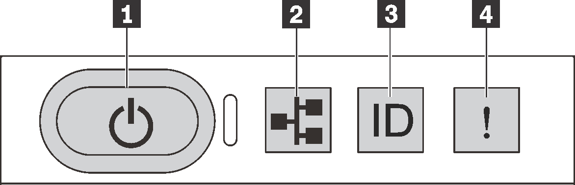
Graphic that depicts the operator information panel of the server. It includes callouts to identify each of the components on the operator information panel.

Table 1. Components on the operator information panel
1 Power button with power status LED2 Network activity LED
3 System ID button with system ID LED4 System error LED

1 Power button with power status LED

You can press the power button to power on the server when you finish setting up the server. You also can hold the power button for several seconds to power off the server if you cannot shut down the server from the operating system. The power status LED helps you to determine the current power status.
StatusColorDescription
Solid onGreenThe server is on and running.
Slow blinking (about one flash per second)GreenThe server is off and is ready to be powered on (standby state).
Fast blinking (about four flashes per second)GreenThe server is off, but the XClarity Controller is initializing, and the server is not ready to be powered on.
OffNoneThere is no ac power applied to the server.

2 Network activity LED

The network activity LED on the operator information panel helps you identify the network connectivity and activity.
StatusColorDescription
OnGreenThe server is connected to a network.
BlinkingGreenThe network is connected and active.
OffNoneThe server is disconnected from the network.
Compatibility of the NIC adapter and the network activity LED:
NIC adapterNetwork activity LED
LOM adapterSupport
ML2 NIC adapterSupport
PCIe NIC adapterNot support

3 System ID button with system ID LED

Use this system ID button and the blue system ID LED to visually locate the server. A system ID LED is also located on the rear of the server. Each time you press the system ID button, the state of both the system ID LEDs changes. The LEDs can be changed to on, blinking, or off. You can also use the Lenovo XClarity Controller or a remote management program to change the state of the system ID LEDs to assist in visually locating the server among other servers.

If the XClarity Controller USB connector is set to have both the USB 2.0 function and XClarity Controller management function, you can press the system ID button for three seconds to switch between the two functions.

4 System error LED

The system error LED helps you to determine if there are any system errors.

StatusColorDescriptionAction
OnYellowAn error has been detected on the server. Causes might include but not limited to the following errors:
  • The temperature of the server reached the non-critical temperature threshold.

  • The voltage of the server reached the non-critical voltage threshold.

  • A fan has been detected to be running at low speed.

  • A hot-swap fan has been removed.

  • The power supply has a critical error.

  • The power supply is not connected to the power.

Check the event log to determine the exact cause of the error.

For information about troubleshooting, see Troubleshooting by symptom .

OffNoneThe server is off or the server is on and is working correctly.None.