System board components
The illustration in this section shows the component locations on the system board.
Figure 1. System board components
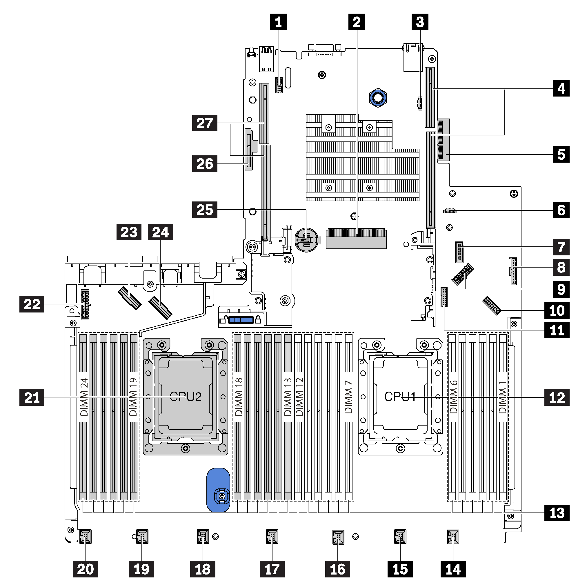
| 1 Serial-port-module connector | 2 RAID adapter slot (slot 4) |
| 3 BIOS ROM programming connector | 4 Riser 1 slot |
| 5 LOM adapter connector | 6 XCC ROM programming connector |
| 7 Front USB connector | 8 Operator-information-panel connector |
| 9 Rear-backplane power connector | 10 Front VGA connector |
| 11 TCM1/TPM2 connector (for Chinese Mainland only) | 12 Processor 1 socket |
| 13 Memory module slots (24) | 14 System fan 1 connector |
| 15 System fan 2 connector | 16 System fan 3 connector |
| 17 System fan 4 connector | 18 System fan 5 connector |
| 19 System fan 6 connector | 20 System fan 7 connector |
| 21 Processor 2 socket | 22 Front-backplane power connector |
| 23 NVMe 2-3 connector | 24 NVMe 0-1 connector |
| 25 CMOS battery | 26 M.2 module slot (SATA/PCIe slot 5) |
| 27 Riser 2 slot |
Note
1 Trusted Cryptography Module
2 Trusted Platform Module
Give documentation feedback