LEDs and buttons on the front operator panel
The front operator panel of the server provides controls, connectors, and LEDs.
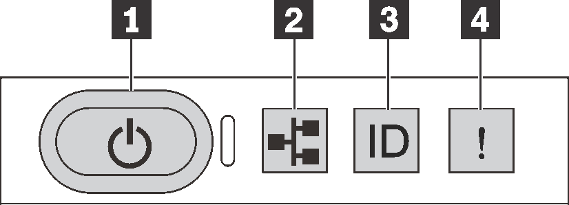
1 Power button with power status LED
| Status | Color | Description |
|---|---|---|
| Solid on | Green | The server is on and running. |
| Slow blinking (about one flash per second) | Green | The server is off and is ready to be powered on (standby state). |
| Fast blinking (about four flashes per second) | Green |
|
| Off | None | Power is not present, or the power supply has failed. |
2 Network activity LED
Compatibility of the NIC adapter and the network activity LED
| NIC adapter | Network activity LED |
|---|---|
| OCP module | Support |
| PCIe NIC adapter | Not support |
| Status | Color | Description |
|---|---|---|
| On | Green | The server is connected to a network. |
| Blinking | Green | The network is connected and active. |
| Off | None | The server is disconnected from the network. Note If the network activity LED is off when an OCP 3.0 module is installed, check the network ports in the rear of your server to determine which port is disconnected. |
3 System ID button with system ID LED
Use this system ID button and the blue system ID LED to visually locate the server. A system ID LED is also located on the rear of the server. Each time you press the system ID button, the state of both the system ID LEDs changes. The LEDs can be changed to on, blinking, or off. You can also use the Lenovo XClarity Controller or a remote management program to change the state of the system ID LEDs to assist in visually locating the server among other servers.
If the XClarity Controller USB connector is set to have both the USB 2.0 function and XClarity Controller management function, you can press the system ID button for three seconds to switch between the two functions.
4 System error LED
The system error LED helps you to determine if there are any system errors.
| Status | Color | Description | Action |
|---|---|---|---|
| On | Yellow | An error has been detected on the server. Causes might include but are not limited to the following errors:
|
Note For server models with L2AM installed, it is required to open the top cover to check the status of liquid detection sensor module LED. For more instructions, see |
| Off | None | The server is off or the server is on and is working correctly. | None. |