
LEDs on the system board assembly

The following illustrations show the light-emitting diodes (LEDs) on the system board (system board assembly).

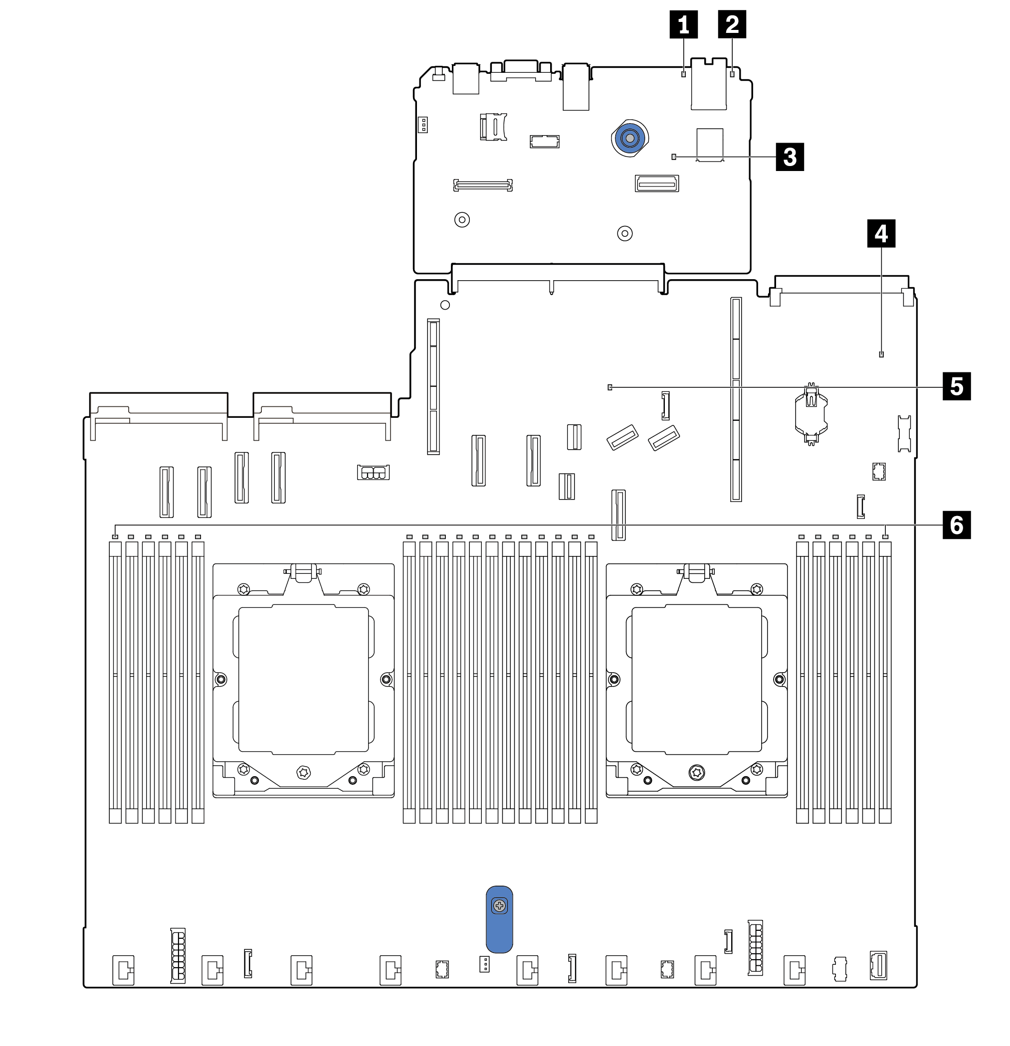
Descriptions of LEDs on the system board assembly

1 System error LED (yellow)

DescriptionWhen this yellow LED is lit, another one or more LEDs in the server might also be lit to direct you to the error source.
ActionCheck system logs or internal error LEDs to identify the failed part. For more information, see LEDs and buttons on the front operator panel.

2 System ID LED (blue)

DescriptionThe front system ID LED helps you locate the server.
ActionEach time you press the system ID button, the state of both system ID LEDs changes, and the state can be on, blinking, or off.

3 XCC heartbeat LED (green)

DescriptionThe XCC heartbeat LED helps you identify the XCC status.
  • Blinking (about one flash per second) : XCC is working normally.

  • Blinking at other speeds or always on: XCC is at the initial phase or is working abnormally.

  • Off: XCC is not working.

Action
  • If the XCC heartbeat LED is always off or always on, do the following:

    • If XCC cannot be accessed:

      1. Re-plug the power cord.

      2. Check and ensure that the system I/O board and the firmware and RoT security module are installed correctly. (Trained technicians only) Reinstall them if needed.

      3. (Trained technicians only) Replace the firmware and RoT security module.

      4. (Trained technicians only) Replace the system I/O board.

    • If XCC can be accessed, replace the system I/O board.

  • If the XCC heartbeat LED is always blinking fast over 5 minutes, do the following:

    1. Re-plug the power cord.

    2. Check and ensure that the system I/O board and the firmware and RoT security module are installed correctly. (Trained technicians only) Reinstall them if needed.

    3. (Trained technicians only) Replace the firmware and RoT security module.

    4. (Trained technicians only) Replace the system I/O board.

  • If the XCC heartbeat LED is always blinking slow over 5 minutes, do the following:

    1. Re-plug the power cord.

    2. Check and ensure that the system I/O board and the firmware and RoT security module are installed correctly. (Trained technicians only) Reinstall them if needed.

    3. If the problem remains, contact Lenovo Support.

4 System status LED (green)

DescriptionThe system status LED indicates the working status of the system.
  • Fast blinking (about four flashes per second): Power fault or is waiting for XCC power permission ready.

  • Slow blinking (about one flash per second): Power off and is ready to be powered on (standby state).

  • On: Power on.

Action
  • If the system status LED is blinking fast over 5 minutes and cannot power on, check the XCC heartbeat LED and follow the actions for the XCC heartbeat LED.

  • If the system status LED remains off or is blinking fast (about four flashes per second) and the system error LED on the front panel is on (yellow), the system is in a power fault status. Do the following:

    1. Re-plug the power cord.

    2. Remove installed adapters/devices, one at a time, until you reach the minimal configuration for debugging.

    3. (Trained technicians only) If the problem remains, capture FFDC log, and replace the processor board.

    4. If the problem still remains, contact Lenovo Support.

5 FPGA heartbeat LED (green)

DescriptionThe FPGA heartbeat LED helps you identify the FPGA status.
  • Blinking (about one flash per second): FPGA is working normally.

  • On or off: FPGA is not working.

Action

If FPGA heartbeat LED is always off or always on, do the following:

  1. Replace the processor board.

  2. If the problem remains, contact Lenovo Support.

6 DIMM error LEDs (yellow)

DescriptionWhen a memory module error LED is lit, it indicates that the corresponding memory module has failed.
Action

For more information, see Memory problems.