Schede retimer (24 porte NVMe)
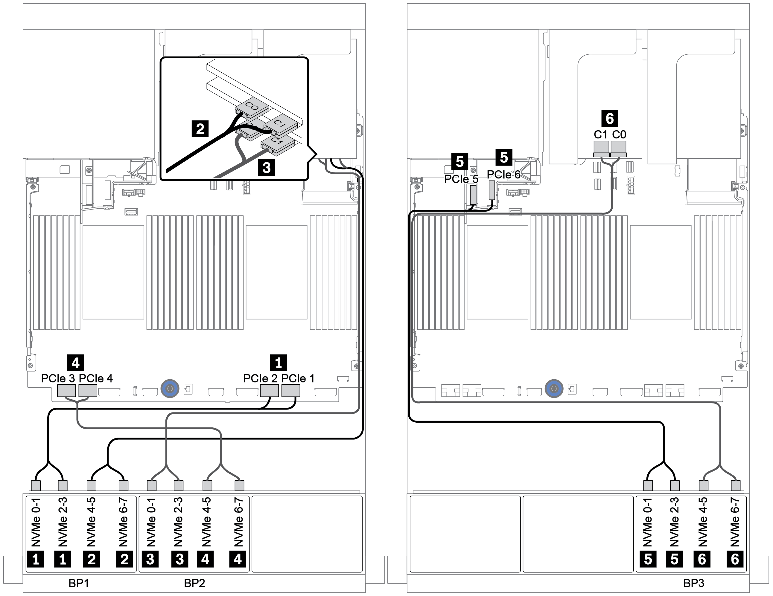
La seguente tabella mostra i collegamenti dei cavi per la configurazione a 24 vani NVMe da 2,5" con tre schede retimer.
| Da | A |
|---|---|
Backplane 1: NVMe 0-1, 2-3 | Integrato: PCIe 1, PCIe 2 |
Backplane 1: NVMe 4-5, 6-7 | Scheda retimer su slot PCIe 1: C0, C1 |
Backplane 2: NVMe 0-1, 2-3 | Scheda retimer su slot PCIe 2: C0, C1 |
Backplane 2: NVMe 4-5, 6-7 | Integrato: PCIe 3, PCIe 4 |
Backplane 3: NVMe 0-1, 2-3 | Integrato: PCIe 5, PCIe 6 |
Backplane 3: NVMe 4-5, 6-7 | Scheda retimer su slot PCIe 4: C0, C1 |
Collegamenti tra i connettori: 1 ↔ 1, 2 ↔ 2, 3 ↔ 3, ... n ↔ n
Figura 1. Instradamento dei cavi per la configurazione a 24 vani NVMe da 2,5" con tre schede retimer
Envoyer des commentaires